Crimped Connectors, What about Reliability and Testing?
- Posted by Mari Carmen López
- On January 13, 2020
- 1
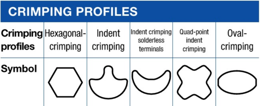
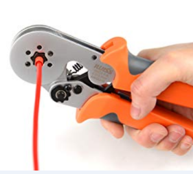
Figure 1. Crimping profiles.
Because of the number and complexity of the factors affecting the crimping quality diverse specifications are devoted to assess and assure the quality depending on the intended application. For instance, due to the strong presence in the automotive industry, several manufacturers have stated their own standards in addition to those from public international agencies.
Table1. Examples of international specifications for crimped connectors.
Indentation depth and dimensional verifications
As fast check, the indentation depth and the width of crimped area has to be measured and verified according to the manufacturer tolerances. However, this measurement only partially evaluates the agreement with to the factory specifications; and more accurate and thorough tests are required in most of the previously mentioned standards in order to assess the actual global performance.
Pull or tensile strength test.
Crimped connectors are devised to fail at a given tensile force. However, this rated strength can only be achieved when adequately performed crimping. The figure illustrates that smaller or larger indention depths (under-crimping or over-crimping) impair mechanical strength. Therefore, under-crimping causes failure by pulling out, whereas over-crimping damages the crimped junction, and the failure is produced by breaking in the crimp. In addition, short pull-out force indicates poor gas tightness, which in turn is related to catastrophic fails due to oxidation and other corrosion phenomena. Hence, a pull or tensile strength test is mandatory in most of the specifications.
The tensile strength test measures the tensile force required to detach (pull out) the crimped ferrule when applying axial stress. In this test, an increasing axial load is applied to the crimped joint until to reach the failure threshold. Pull rate (i.e., the rate at which the wire and the terminal are pulled apart) is a relevant factor affecting the ultimate pulling force indicated in some specifications. Special attention must be paid to this point to obtain a reliable test result.
Metallographic cross-section inspection.
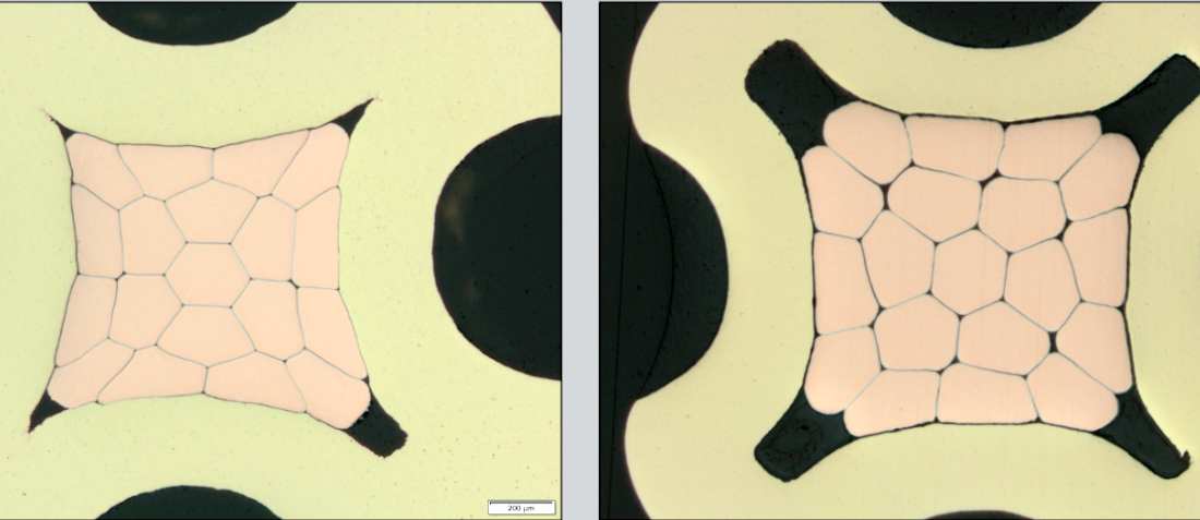
Metallographic or micros-section inspection is mandatory in several regulations including ECSS specifications required by the European Space Agency (ESA) projects.. For this inspection, the connector is cross-sectioned in order to gain access to the internal structure of the crimped area. This allows us to deeply assess the real quality of the crimped area by analyzing several critical factors such as the void percentage, the barrel and wires deformation, braids distribution and the barrel and wire integrity (cracks formation and plating delamination). For instance, specification ECSS-Q-ST-70-26C, used in ESA projects, states that “voids occupy less than 10 % of the cross-sectioned area of the wire”. In addition, it also indicates that barrel shall not present cracks or other damages induced by the crimping process. The figure compares rejected and accepted cross-sections according to both criteria analyzed in our laboratory.
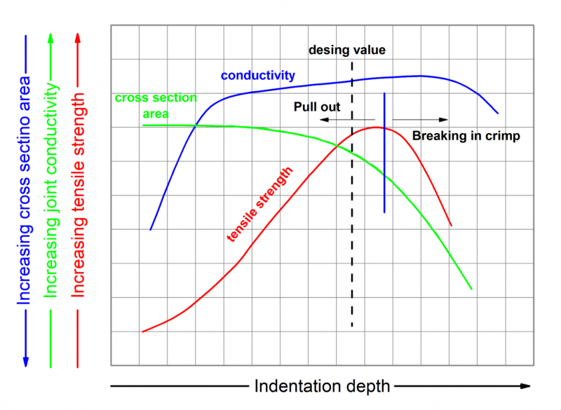
Figure 2. Variation of crimped connector characteristics with the indentation depth. Modified from RADC-TR-78-15, Crimp Connection Reliability, Air Force Systems Command.
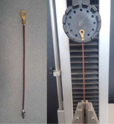
Figure 3: Typical test fixture for testing lug and splice crimps (ECSS-Q-ST-70-26C)
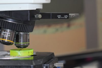
Figure 4: Metallographic inspection
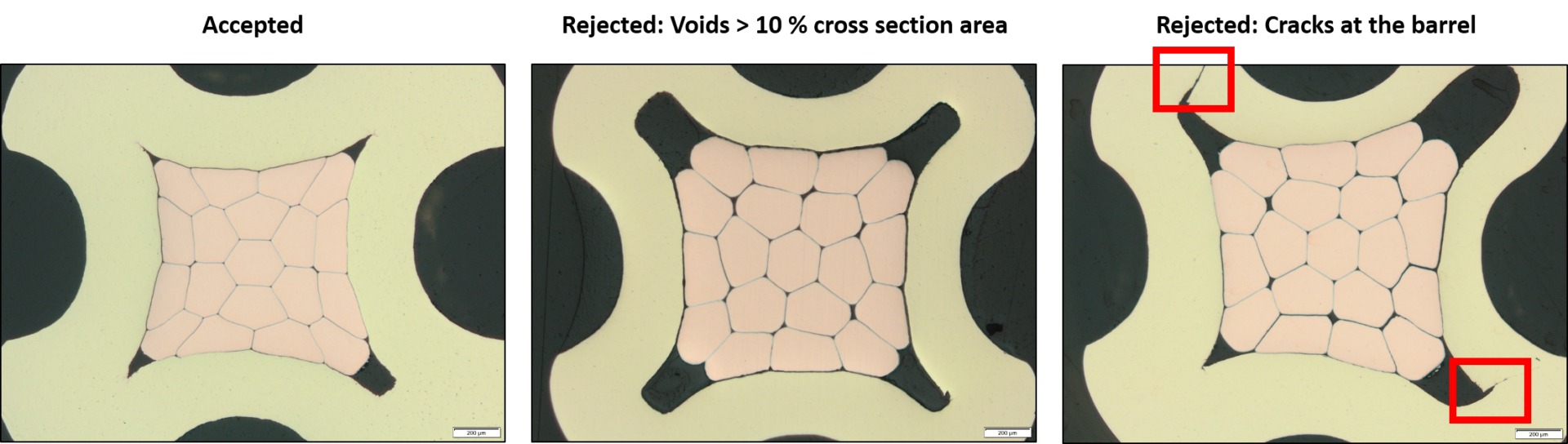
Figure 4. Examples of Connectors rejected and accepted iaw the specification ECSS-Q-ST-70-26C.
The used methodology (preparation steps) and materials (cutting tools, clothes, lubricants, and abrasive media for gridding and polishing) must be specifically adapted to the materials forming the inspected connectors. Alter Technology has laboratory dedicated to these processes and accumulates a high degree of expertise in these activities. The suitable selection of the microsectioning strategy permits to obtain the actual internal structure, free of features related to improper micro-section approaches.
Metallographic cross-section inspection of crimped connectors is typically performed by optical microscopy. However, thorough failure analyses also require combining micro-analytical tools (EDX) and advanced electron-microscopy techniques (Hi-Resolution SEM) in order to study the presence of corrosion products at the barrel and wires surfaces. The figure shows one of these analyses carried out by Alter Technology during the failure analyses of a crimped connector.
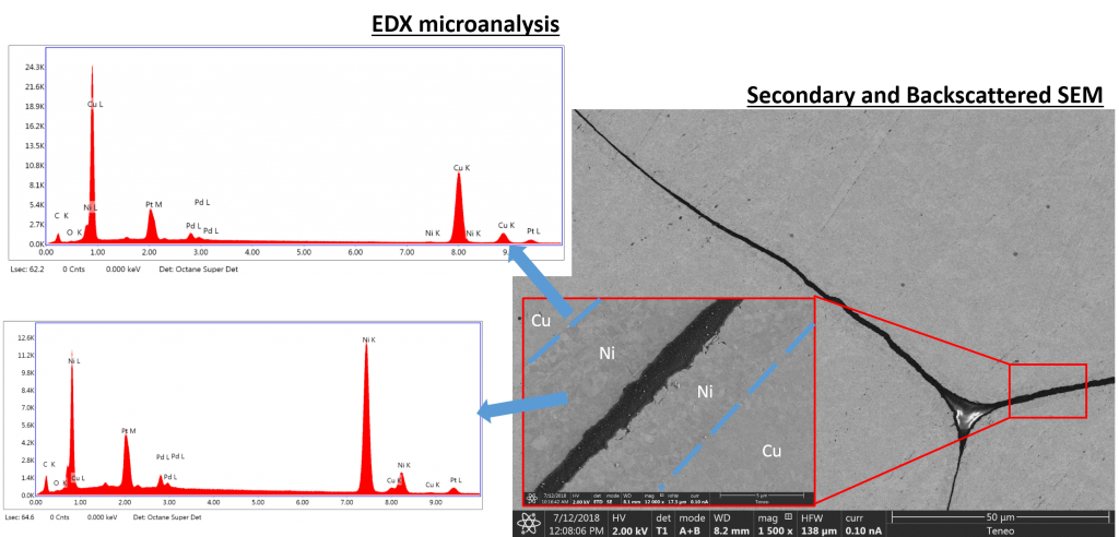
Figure 5: Additional Microanalyses.
Verification and inspection of Hi-Rel crimped concertos is a highly-specialized task that require qualified staff. With this concern ESA trains and certifies inspectors for of such activities. As a representative example of the Alter Technology commitment to quality, crimped-connection inspection is conducted by highly qualified and ESA certified staff. Similarly, micro-sectioning is a delicate process that can induce misleading results
Being this a critical issue that does not only depends on the laboratory protocol but also on the skills and training of the technical team conducting the activities, ESA selects those laboratories that according to the higher quality standards are recommended to perform such operations on SMT/PCB systems. It is worth mentioning here that due to the high-level standard that Alter Technology maintains in all its activities it is currently an ESA recommended laboratory to conduct metallographic inspections in SMT systems.
Authors: Francisco Javier Aparicio Redondo & Mari Carmen López López
Head Of Materials and Processes Laboratory
Mari Carmen has a degree in Degree in Chemistry and a PhD. in Materials Science.
She is responsible for the Materials & Process Laboratory of Alter Technology. Her work is focused on investigating the effects of the environment on electrical components, materials, and processes. As the head of the laboratory, she also manages the studies conducted to evaluate the quality of a bare or assembled printed circuit board in relation to ECSS standards or according to the customer’s specifications.
- Why Microsectioning sample preparation of PCB systems? - May 19, 2021
- Inspection of conformal coating on PCB using UV Light - August 4, 2020
- Plating Thickness Testing Overview in Alter Technology Lab. - July 28, 2020
1 comments on Crimped Connectors, What about Reliability and Testing?