Flow Stages in Vibration Testing on Hi-Rel EEE Parts
- Posted by María Teresa Rodríguez
- On May 25, 2019
- 0
Flow Stages in Vibration Testing for space applications.
Depending on the intended application electrical components are exposed to either transitory or permanent dynamic mechanical stress which can impair the performance (e.g. mechanically induced crack in PCBs systems or fretting corrosion in connectors and others).
In order to ensure the proper system operation under such conditions, High-Rel EEE parts have to be submitted to thorough vibration test before their implementation in different areas. These tests must be carried out according to different specifications depending on the application areas, such as those included in the following table.
Vibration Tests on HI-ReL
| wdt_ID | Title | Reference | Organization | Parts |
|---|---|---|---|---|
| 1 | Manual soldering of high-reliability electrical connections | ECSS-Q-ST-70-08C | European Cooperation for Space Standardization (ECSS) | Sodered system including Surface mounted devices (SMD), printed circuit boards (PCB) |
| 4 | High-reliability soldering for surface-mount and mixed technology | ECSS-Q-ST-70-38C | European Cooperation for Space Standardization (ECSS) | Sodered system including Surface mounted devices (SMD), printed circuit boards (PCB) |
| 7 | Generic Specification for Connectors Electrical Non-Filtered Circular and Rectangular | ESCC 3401 | European Space Components Coordination (ESCC) | Connectors |
| 10 | Test Method Standard, Microcircuits | MIL-STD-883 TM2005 / TM2006 / TM2007 / TM2026 | Defense and Logistic Agency | Microcircuits |
| 13 | Test Methods for Semiconductor Devices MIL-STD-750 TM2016 TM2046 TM2051 TM2056 TM2057 | MIL-STD-750 TM2016 / TM2046 / TM2051 / TM2056 / TM2057 | Defense and Logistic Agency | Semiconductors |
| 16 | Test Method Standard, Microcircuits MIL-STD-202 TM201 TM204 TM214 TM213 | MIL-STD-202 TM201 / TM204 / TM214 / TM213 | Defense and Logistic Agency | Component parts |
| 19 |
Solving A Widespread Pain Using DoEEEt,
Navigate clicking here ⇒

Application areas:
- Defense/Military
- Aerospace
- Automotive
- Space
- …
Space environment
Electrical equipment in rocket boosters and spacecraft are subjected to high dynamic loads and mechanical shocks of different nature. Space launch involves low-frequency vibrations generated during lift-off, motor excitation, buffet, and shut-offs. In addition, large shock-loads are experienced during the space trip, particularly in pyrotechnic separation stages which also involves high-frequency shock waves.
Such dynamic loads are responsible for different failures modes in EEE systems. For instance, excessive deformations and accelerations (g-loads) experienced by assembled-system parts cause heavy damage in connectors, surface mounted devices (SMD), printed circuit boards (PCBs) and similar electrical components.
A clear example of a vibration induced failure in SMD systems is PAD cratering in BGA, CGA, and bottom termination components. Hence, the ability to simulate, in the ground, this mechanical stress or the capacity to investigate structural dynamic characteristics is critical for the successful qualification of new EEE part for space applications.

Figure 1.
Test flow
In order to illustrate the different tests that are conducted within a full vibration study, the next figure shows the stages of a typical vibrations test performed according to the ESCC specification ECSS-Q-ST70-08C followed in ESA (European Space Agency) projects.
These tests are grouped in two blocks corresponding to high-level i) sine-sweep high and ii) random vibrations that must be applied independently over three orthogonal axes. As it is indicated in the test flow each high-level vibration, either sine or random, is preceded and followed by low-level sine-vibration surveys in order to analyze the modification induced in the mechanical properties (e.g. development of resonant features) of the device under test (DUT) as it is explained below.
The main contributing factors include PCB thickness, size, resin type, CTE of the PCB and component, solder type, component position, assembly condition and post assembly handling. There are some strategies to mitigate the appearance of Pad Cratering failure, such as:
- Epoxy fillets at devices corners
- Increase board thickness to eliminate flexing
- Increase pad or trace widths
Since the initiation of pad cratering does not result in an instantaneous electrical signature, detecting the onset of this failure has been challenging. For instance units with pad cratering may not fail during functional test and Microsectioning Analysis remains the most widely accepted means for analyzing the Pad integrity.
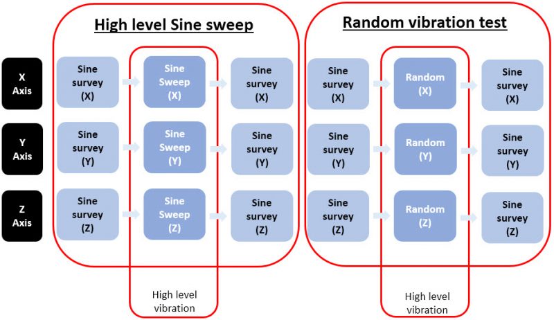
Figure 2. Vibration test flow for ESCSS-Q-ST70-08C.
Types of Vibration Testing
The main objective of vibration testing is to simulate the stress conditions (types of stress, load level and frequencies) that are expected the component has to endure. The two main kinds of vibrations used for this purpose are sine-sweep and random vibrations. Nevertheless, other mechanical motions such as since burst and mechanics shock are also commonly used to analyse the suitability of EEE components.
Pre-Tests
Low-level Sine-survey
Vibration Testing is the first approach to determine the mechanical weaknesses of the DUT the system is submitted to a sinusoidal stimulus of increasing frequency as illustrated in Figure 3. A logarithmic sweep rate is traditionally used to compensate the longer time required to complete a cycle at the lower frequencies.
As it is indicated in Figure 3 low-level sine-survey vibrations are conducted before high-level tests. This precaution is taken in order to analyze the mechanical impedance of the test-fixture/DUT assembly within the inspected frequency range. Such a low-level pre-test allows us to assess in a safe manner the natural frequencies of the system in order to avoid excessive damage due to nonlinear responses.
For instance, printed circuit boards may present strong resonant responses within the tested frequencies range. At that resonant frequencies the mounted devices and the solder joints on the PCB would be submitted the extreme accelerations, much higher than the applied by the testing system. Preliminary studies conducted in our lab either with dummy (high level pre-test) and real system (low level pre-test) are intended to avoid such adverse effects.
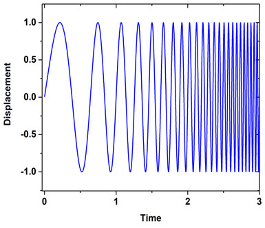
Figure 3: Constant displacement sine sweep (time domain)
Moreover, using sine vibration to identify resonant conditions on the PCB or other systems is an effective way to understand how mechanical vibration propagates through a device and can help designers to improve the designs of the item by stiffening or soften elements and to reduce the probability of a fatigue failure.
Low-level sine-survey is also performed after each high-level vibration. This additional analysis is performed to reveal the effect of high dynamic loads on the mechanical properties of the system. Therefore, any difference detected between the pre-test and post-test low-level sine survey responses (e.g. natural frequencies shift of development of new resonances) must be taken as indications of damage.
High level sine-sweep
Similarly to low-level sine-survey, during this test the system is subjected to an uniaxial sinusoidal movement of increasing frequency. Moreover, the acceleration (∝ displacement x freqcuency2), is modified depending on the used test profile. As an example, Figure 4 shows the frequency domain graph (acceleration vs frequency) for a test where the acceleration linearly increases with the frequency up to a given constant value. This kind of test are used to assess the effect of periodic and semi-periodic large loads on the DUT.
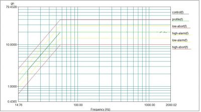
Figure 4. Sine vibration test frequency graph
Random Vibration
In real applications, sine vibrations are rear and not representative of the real conditions experienced by the DUTs. For instance, dynamic stress generated in real scenarios is, in general, not periodic or predictable like sinusoidal waveforms. In fact, the majority of vibration environments where electronic devices are mounted applies random vibration conditions.
In order to simulate a more realistic dynamic stress, random vibration test simultaneously excites all the frequencies within a given range. The stimulus is applied in a semi-random way with a spectrum that constantly changes in amplitude and phase. Nonetheless, the process is not completely stochastic as the average level is adjusted to follow a given test profile as illustrated in Figure 5. By this way, the vibration level is maintained with the limits stated to ensure that the test reproduces the working conditions of the DUT and that the test is conducted under safe conditions.
In this test, the vibration profile is defined in the frequency domain and analyzed in power spectral density (aceleration²/Hz), units which provide more meaningful info about the applied dynamic stress. This signal is applied to the DUT for a given amount of time to verify the device functionality under such conditions.
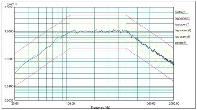
Figure 5. Random vibration test frequency graph.
Additional Test
Sine burst
Sine burst represents an effective alternative to static mechanical tests used to study the strong resistance of electrical component (tensile and flexion tests). In this test, a single frequency sinusoidal signal is applied whereas the acceleration gradually increases until to reach the target load. The load level may reach high values. Therefore, the selected test frequency must be below the natural frequencies of the system in order to reproduce the effect of a static load, usually at least 1/3 of the first resonant modes. Therefore, it is mandatory to conduct low-level sine survey pre-test to determine the DUT resonant modes. It is also recommended performing additional single frequency pre-test at intermediate load-levels to verify that the target loads can be safely achieved.
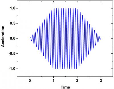
Figure 6: Sine burst (time domain)
Mechanical shock testing
The aim of mechanical shock testing is to assess the response and stability of the system under severe shocks (extreme acceleration and deceleration processes) e.g. to those produced during flight operations, pyrotechnic separation and others. Forecast of response for printed circuit boards due to shock loads is quite important for the mechanical design step and reliability of electronic packages. The control system will reproduce the time domain of the selected waveform at the defined acceleration level and duration.
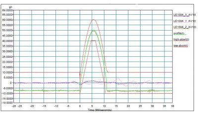
Figure 7. Mechanical shock test time graph.
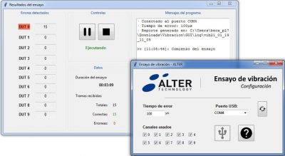
In-situ electrical monitoring
Optionally, during each vibration test, the main electrical characteristics of the systems can be monitored with a dual purpose:
- Early detection, in-situ, of mechanically induced electrical fails.
- Detection of transient electrical discontinuities only detected under vibration stress.
In this regards, the figure shows an monitoring system developed to analyse electrical discontinuities during this and other environmental and radiation test. In this example the system is programmed to register short discontinuities of 1 µs or longer, i.a.w. the specification MIL-PRF-32192, issued by the DLA, and the system allow us to register shorter discontinuities until 100 ns.
Final inspection and measurements.
All the described tests are conceived to study the effect of dynamic stress on EEE parts and other systems. Therefore, after completion the DUT must be thoroughly inspected and analyzed in the search of structural anomalies and/or malfunction sings. Alter Technology gather a large variety of in-house services for the final electrical characterization and physical inspection of the tested systems.
Inspections services:
- Internal Microsection inspection
- Non-destructive external inspection
- Non-destructive internal inspection by X-ray and Acoustic Tomography.
- Electrical testing services
Contact us for more information
Previously, she was responsible for the area of component vibration (mainly sine and random tests). In addition to these tests, she was in charge of designing the tools necessary for the correct fixation and positioning of the elements to the equipment. On the other hand, she also worked as a quality inspector. Also, she carried out tests in the materials and processes laboratory area, where her work focused on micro-sectioning and the subsequent evaluation of electronic components. Also, she was part of the areas of electrical measurements and destructive testing, DPA. In these areas, her functions were the analysis and verification of passive components and microcircuits. She was in charge of the technical review of reports and the performance of CSAM tests, respectively.
Before joining Alter Technology, she participated in the SPADE Project in the REXUS/BEXUS program at ESA’s Education Office, where she was in charge of the design and adaptation of all the electronic parts and components of the project and for which she received training through a course on aerospace welding, by experts in the field from ESTEC (ESA’s main center); Alter was one of the main sponsors of this project, actively participating in several stages of it.
- Virtual Vibration Laboratory - February 8, 2021
- Vibration Services & Acreditations - February 8, 2021
- Vibration Laboratory Equipment - February 8, 2021
0 comments on Flow Stages in Vibration Testing on Hi-Rel EEE Parts