Logo
  • Resources
    • COTS for Space WEBINARS
    • ACCEDE 2022 Workshop on COTS
    • EEE COMPONENTS
    • SPECIFICATIONS / QPLs
    • EVENTS / WEBINARS
    • SPACE TALKS
    • TECH ARTICLES
    • MANUFACTURERS NOTIFICATIONS
  • Laboratory Services
    • LABORATORY STANDARD TESTING
    • NON STANDARD TESTING
    • SILICON CARBIDE -SiC- DIODES
    • CROWDTESTING
    • OPTOELECTRONICS
    • SMALL SATS
    • REPRESENTATIVE PROJECTS / PAPERS
  • Additional Services
    • INDUSTRY 4.0 CYBERSECURITY (IEC 62443)
    • PENETRATION TEST
    • CYBERSECURITY CERTIFIED (CSC)
    • CODE SCORE MATRIX
    • LONG-TERM STORAGE OF WAFERS
    • ELECTRONIC DESIGN
  • Tools
    • COMPARATOR
    • MY DCLs/BOMs
    • STOCKPLACE
  • About Us
  • My Request
  • Sign In
Blog Image
PHYSICAL, MECHANICAL & ASSEMBLY, TESTING

DC power – Use of Substrate Attach Strength – Die Shear Strength Method

  • Posted by José Cándido Vázquez Cárdeno
  • On February 13, 2019
  • 0

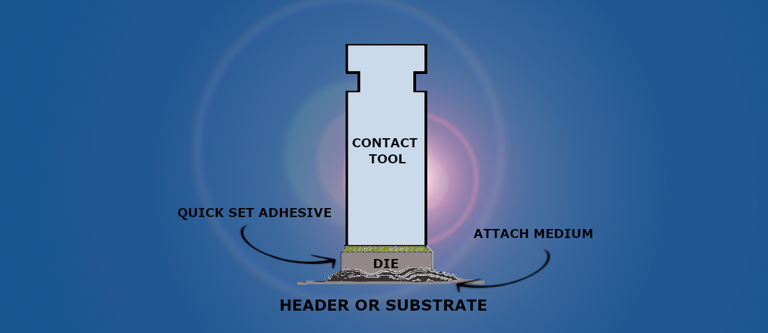
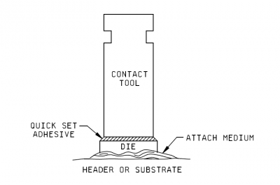
The purpose of the test is to determine the strength of the element attachment system when subjected to force in the Y1 axis, and thus to determine the integrity of materials and processes used to attach semiconductor die or surface mounted elements to package headers or other substrates. The implementation of this test includes material evaluation and process control.

Development, volume, and weight of such power units and power rails contribute to the costs of space missions. At the same time, the power distribution to the modules with low voltages and high currents requires heavy power rails due to large cross-sections or suffers from conduction losses or both.

DC power

As DC power is supplied to extended distances from the source, the system bus power is delivered at a much higher bus voltage in order to reduce weight and resistive power loss. System source voltages are commonly a nominal 12V, 28V, 48V, 120V and in some cases 270V.

Power conversion is typically accomplished in multiple stages to reach the final load voltage. Isolation and regulation are two key requirements and may be implemented at different stages depending on system architecture. Although power is lost at each conversion step, it is not practical to deliver the lowest voltages over significant distances due to the high currents and consequent high resistive losses which would be incurred. Designers must balance the advantages and disadvantages of multi-stage power conversion, the tradeoffs of distance, and the need for intermediate voltages to power other circuit elements that often drive the architecture.

The multitude of low-voltage, high current loads and increased system power efficiency requirements make yesterday’s typical design approaches less practical, and design requirements more difficult to achieve.

Traditionally, there are at least two basic design approaches for most power design solutions.

One common solution is a decentralized approach where several isolated DC-DC converters operating directly a space craft power bus (or just one with several outputs), which provide the regulated supply voltages, 1V, 1.5V, 2.5V, 3.3V, 5V, etc., as required by the digital loads.

DC power

DC power

Get a quick price/delivery estimation of your components, being the first in front of your customer

doEEEt.com The only database of Hi-rel parts for use in Space, compare components from different manufacturers and get recommendations based on your needs.

MICROCIRCUITS

Microcircuits

Components: +36300

Qualification Status Rate: + 78 %

DISCRETES

Discretes

Components: + 60.000

Qualification Status Rate: + 61 %

Continue reading about power distribution
References
  • Author
  • Recent Posts
José Cándido Vázquez Cárdeno
Laboratory Specialist at Alter Technology
José Cándido has a Doctoral Thesis on High-Efficiency Industrial Solar Cells.
He works as a technical specialist in the Laboratory of destructive physical tests in Alter Technology.
José Cándido Vázquez Cárdeno
Latest posts by José Cándido Vázquez Cárdeno (see all)
  • Radiographic Inspection 3D X-Ray – 2D - September 14, 2020
  • SOLAR CELLS - February 24, 2020
  • DC power – Use of Substrate Attach Strength – Die Shear Strength Method - February 13, 2019
TAGS: DPA EEE PARTS DIE SHEAR TEST EVALUATION QUALIFICATION Testing Method

Previous Post

Test Methods in Electronic parts. The Vibration Tests

Next Post

DPA parts examination used for Electrical Components
0 comments on DC power – Use of Substrate Attach Strength – Die Shear Strength Method
Recent Posts
  • Miniature RF Connectors
  • Miniature RF Connectors for high-performance testing
  • Space-Grade components available for immediate delivery
  • Introduction to RD ALFA Microelectronics: Components and Capabilities
  • Managing EEE components for LEO and lower cost space missions
Scroll

doEEEt.com

DoEEEt: Electrical Electronic Electromechanical (EEE) parts database. Find (EEE) components/parts products and datasheets from hundreds of manufacturers.

Privacy Policy and Legal Notice

Copyright

Cookie Policy

Copyright © 2021 ALTER TECHNOLOGY TÜV NORD S.A.U

Company

About us

Contact us

How does doEEEt works? – FAQ

ALTER Laboratory Services

Microwave and RF Testing

Small Sats Testing

COTS components Testing

Authenticity Test