Derating and Category Concepts for Capacitors
- Posted by Tomáš Zedníček
- On January 14, 2020
- 0
Category Concepts and Derating
Recommendation for voltage derating means that the actual capacitor shall be used in the application at a lower voltage than the rated voltage. Derating is expressed usually by a percentage of rated voltage that shall be subtracted. For example, 20% derating means that the capacitor shall be used at 80% of rated voltage at the specific applications (10V capacitor to be used on 8V maximum).
The purpose of the derating is to reduce the amount of load accelerating factors to the capacitors. The two main accelerating factors are voltage and temperature.
As per the equation, C1-20 energy content is depending on voltage squared, thus voltage reduction (voltage derating) has a significant impact on overall energy handling through the capacitor. Reasons for voltage derating can be varied depending on the capacitor technology, construction, and applications. The main general reasons for voltage derating can be as follows, nevertheless, it may be good to study the capacitor manufacturer’s application guidelines.
- high operating temperature derating (“temperature derating”) and category concepts
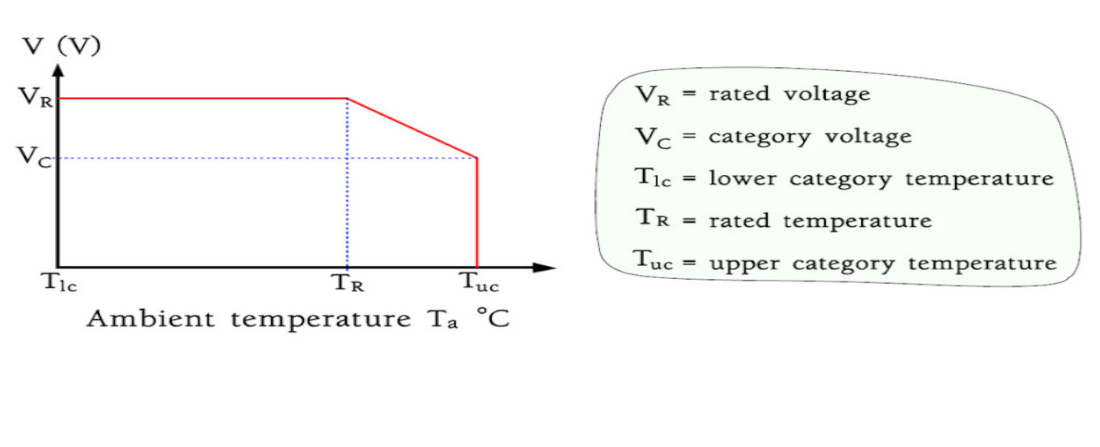
Capacitors designed for DC voltages produce no internal heating. Therefore they often can be used with more or less reduced voltages up to the so-called upper category voltage where the temperature characteristics of the material put a limit. This occurs at the upper category temperature, TUC, in other nomenclatures called maximum usage temperature. The connections are shown in the following Figure below. Varying derating curves are shown in MIL-HDBK-1547.
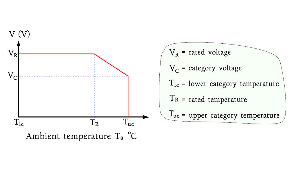
Figure: Typical voltage derating at the upper category temperature.
Note: derating due to the high operating temperature (see below) is sometimes called “temperature derating”, but this may cause some confusion. Degradation mechanisms are usually accelerated by both temperature and voltage factors, just with different root coefficient and predominant impacts. Thus the term “temperature derating” should be left to “limitation of use of the capacitor at lower than rated temperature due to a predominant temperature is driven physical degradation mechanism”. In other words, we need most to have a voltage derating in place to limit the amount of overall energy in the capacitor, but in some cases degradation process is accelerated more by temperature factor (and we want to limit this by the limitation of maximum exposed temperature “temperature derating”)
- surge current load limitation
Some capacitors, such as tantalum solid capacitors, may have a limitation in its maximum allowed current surge spike. Current surge overloading may cause in some cases even thermal destruction and fatal failures in some cases. The practical method to increase the surge current load capability is to use a higher voltage capacitor, in other words, use higher voltage derating. The derating recommendation may be then dependent to circuit function, application or specific capacitor technology.
As an example of solid tantalum capacitors the basic rules are:
tantalum MnO2 capacitors: 50% derating in high current surge applications (such as input side of DC/DC converters or directly on battery), 20% for other applications (coupling, timing, DC/DC output)
tantalum polymer capacitors: 10% for all circuits for <= 10V capacitors, 20% for all circuits for >10V capacitors
These derating guidelines are typically specified to 105°C (temperature derating). Additional derating may be necessary up to 125°C.
- reliability improvement
voltage is one of the strongest accelerators for the number of failure mechanisms and thus its reduction may significantly improve the component reliability.
As an example aluminum electrolytic or film capacitors lifetime is strongly influenced by applied voltage and voltage derating is the most effective way to increase lifetime and reduce MTBF rate.
- capacitors electrical parameters stability (MLCC capacitors)
the voltage may play an important inhibitory role in a number of mechanisms. High K Ferro-dielectrics such as BaTiO3 used in Class II MLCC capacitors are featuring strong dependency of capacitance value to AC and DC voltage (DC BIAS voltage impact). The applied voltage is also a condition for piezo-effect that may cause harmful audio noise generation by MLCC class II capacitors.
Voltage derating may significantly suppress these phenomenons and thus improve the performance of MLCC class II capacitors.
Multiplication of derating requirements
Different voltage derating requirements are usually in “OR” logic,”whatever is greater” relation. It means that the greatest derating principle is applied only.
An example: 12V input side of DC/DC converter (high surge current load application). Maximum operated temperature of end devices: 125°C and 105°C. Can we use 16V tantalum polymer or tantalum MnO2 capacitors?
- 125°C device with tantalum polymers: 20% voltage derating is recommended for 16V tantalum polymer capacitor in all applications and there is also 33% derating needed at 125°C (no derating to 105°C). You can apply maximum 10.7V to the capacitor for the entire operating temperature range to 125°C (voltage derating 20% is covered by the 33% temperature derating). Thus 16V capacitor is NOT suitable for 125°C device due to the high temperature. Need higher rated 20V tantalum polymer capacitor.
- 105°C device with tantalum polymers: there is no derating due to the temperature at 105°C, thus 20% derating for all circuits would apply only. It means 16V tantalum polymer capacitors CAN BE USED used up to 12.8V in the 105°C entire temperature range.
- Can tantalum MnO2 capacitors be used? Tantalum MnO2 capacitors require 50% derating for hard surge current applications, thus 25V capacitors have to be used in this application. There is also 33% derating for 125°C device, but this is not effective as the 33% derating due to temperature is covered by the 50% derating due to the surge current limitation. 16V tantalum MnO2 capacitors can be used at other non-surge critical circuit applications (output of the DC/DC, timing, coupling …) reflecting the 20% derating rule due to the surge and the same derating due to the temperature as tantalum polymer capacitors.
EPCI | Bringing Passive Professionals Together
Electrotechnology Degree by Technical University of Brno, the Czech Republic in 1993
Ph.D. in Tantalum Capacitors in 2000
> 21 years working for tantalum capacitor manufacturer
> 15 years in a position of Worldwide Technical Marketing Manager
more than 60 technical papers and 1 US/international patent
4 outstanding/best award technical papers at CARTS passive component conference
2005 Dr. Zandman award for a great contribution to the passive component industry
Lecturer of capacitor technologies, presentation skills, and inter-culture communication
July 2015 – Founder of the European Passive Components Institute
- Why low ESR matters in capacitor design - May 24, 2021
- Voltage and Frequency Dependence on Resistors - March 6, 2021
- Permeability concept in Inductors - March 4, 2021
0 comments on Derating and Category Concepts for Capacitors