This article is the first part of a complete installment on the construction, manufacture, application and characteristics of ceramic capacitors, divided into 4 sections:
- Introduction to ceramic capacitors
- Construction & manufacturing process
- Ceramic capacitors class 1
- Ceramic capacitors class 2
Ceramic dielectric electrostatic capacitors are dominating the capacitor market in several fields:
- Largest volume capacitor technology (by far)
- Largest value capacitor technology
- Smallest dimension discrete components among all passives
- High flexibility of design to meet specific requirements such as low ESL / high-frequency operation
- Strong presence in both low voltage, low power and high voltage, high power applications
Despite all the above benefits, the technology has some limitations that must be understood for the correct use and design.
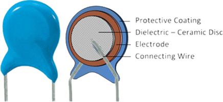
The basic construction types include simple single-layer SLCC and major types made using stacking technology, such as MLCC multilayer ceramic capacitors.
Single layer (SLCC)
- simple construction
- low-cost technology
- lower CV
- higher ESR
- wide voltage range
- high voltage, high power applications
- RF/microwave applications
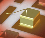
Wire bonded single layer ceramic chip in RF application
Multilayer (MLCC)
- mass volume
- miniaturization
- low ESR
- high CV
- flexible technology
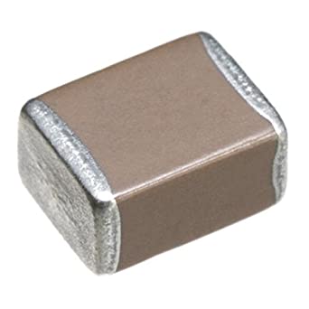
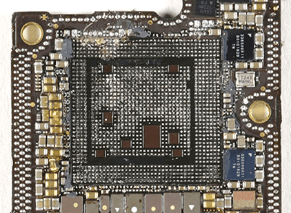
Example of high density MLCC on board of smartphone around and under the main processor (removed)
MLCCs chips are the leading downsizing and miniaturization technology among passive components. The chart below illustrates the shift of the case size mix in MLCCs. While the most popular case size in 1995 was 0805, 0603 in 2000, and 0402 in 2009, the most often used case size since 2018 is 0201, which is a capacitor in dimensions 0.6×0.3×0.3mm. The smallest MLCC in mass manufacturing is the 008004 cases introduced to volume production in 2019, with dimensions as small as 0.2×0.1×0.1 mm.
The enormous volumetric downsizing is illustrated in Figures 1. and 2. below – about the same volume taken by 10 pieces of 1210 case size is occupied by 100 000 pieces of 008004 capacitors!
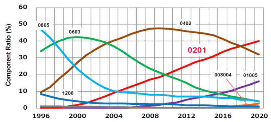
Figure 1. MLCC ceramic capacitor case size share trend; source: Murata
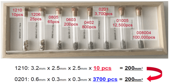
Figure 2. MLCC ceramic capacitor case size volumetric comparison; source: Murata
Ceramic dielectric classifications
The different ceramic dielectric materials used for ceramic capacitors, including linear (paraelectric), ferroelectric, relaxor-ferroelectric, or anti-ferroelectric behaviour (Figure 3), influence the electrical characteristics of the capacitors. Using mixtures of linear substances mostly based on titanium dioxide results in very stable and linear behaviour of the capacitance value within a specified temperature range and low losses at high frequencies. However, these mixtures have a relatively low permittivity, so the capacitance values of these capacitors are relatively small.
A specific group of materials is anti-ferroelectric dielectrics. In contrast to ferroelectrics, where permittivity decreases with applied voltage, antiferroelectric permittivity is low at low voltage and increases with electric field / applied voltage. These materials can achieve high CV and high capacitance at high voltage applications such as energy generation or EV/HEV vehicles in the automotive industry. See Figure 3. below for a comparison of polarisation curves between linear dielectrics (class 1), ferroelectrics (class 2), and anti-ferroelectric materials. We will discuss more in class 2, the chapter on ceramic capacitors.
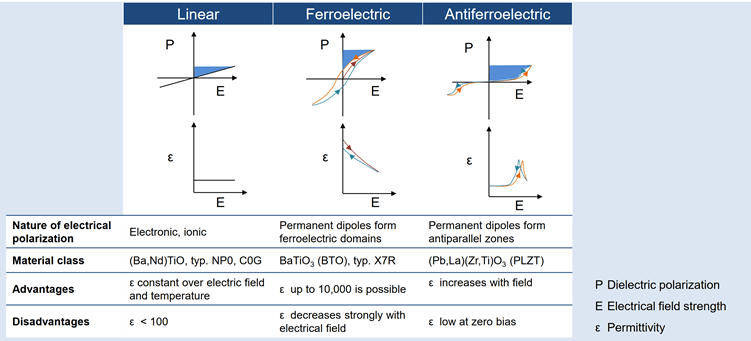
Figure 3. ceramic capacitors PE curves for linear, ferroelectric, and antiferroelectric dielectrics; source: TDK
Higher capacitance values for ceramic capacitors can be attained by using mixtures of ferroelectric materials like barium titanate together with specific oxides. These dielectric materials have much higher permittivities, but at the same time, their capacitance value is more or less nonlinear over the temperature range, and losses at high frequencies are much higher. These different electrical characteristics of ceramic capacitors require grouping them into “application classes.”
The definitions of the application classes given in the two standards are different. The following table shows the different definitions of the application classes for ceramic capacitors:
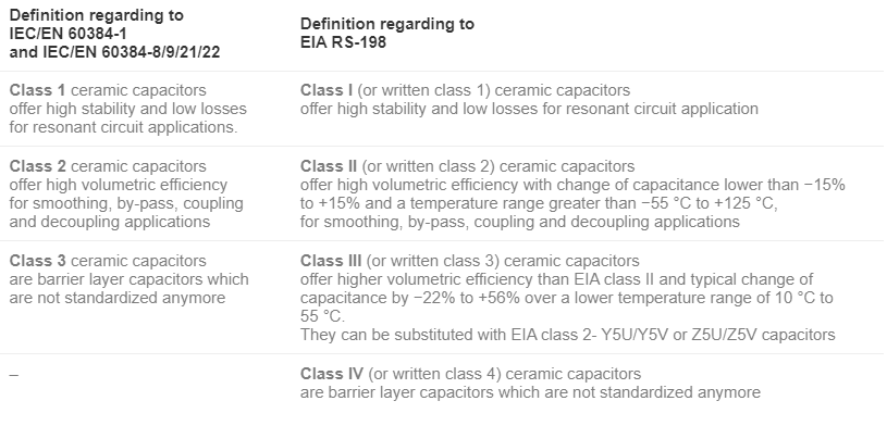
Table 1. Ceramic dielectric material classifications
Continue reading on: 2. Construction & manufacturing process.
Source: EPCI
