Tantalum and Niobium capacitors belong to electrolytic capacitor types, and they are known for their high capacitance in small dimensions (high energy and power density), reliability and stability of its parameters.
Traditionally, tantalums’ advantages over aluminum electrolytic capacitors have been found in terms of capacitance per volume, parameter stability over temperature, and longevity; tantalums, in general, do not suffer from dry-out problems or issues of dielectric degradation when stored and discharged for long periods. However, tantalums are generally more costly and have a more limited range of available capacitance and voltage values.

Table 1. Tantalum capacitor’s key features and benefits
The main types include:
- Tantalum solid electrolytic capacitors
- with MnO2 electrolyte
- with conductive polymer electrolyte
- Niobium and NbO solid electrolytic capacitors with MnO2 electrolyte
- Tantalum wet electrolytic capacitorshea
We will learn more about these types in the following chapters.
Construction and manufacturing process
Tantalum capacitors are manufactured from a powder of relatively pure elemental tantalum metal. Niobium capacitors from niobium metal powder and NbO capacitors from NbO powder with metal-like properties.
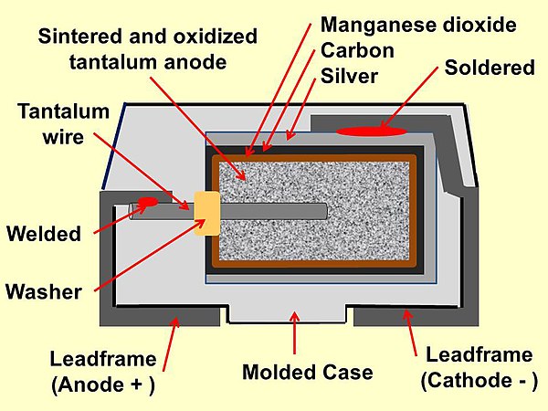
Figure 1. Construction of a typical MnO2 solid electrolyte tantalum capacitor
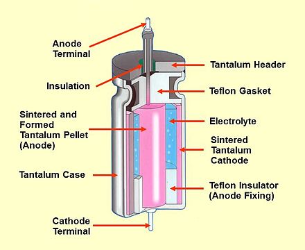
Figure 2. construction of conventional wet electrolyte tantalum capacitors
The following manufacturing process chart describes the standard tantalum chip MnO2 solid electrolyte manufacturing flow. The process is identical also for niobium and NbO chip capacitors.
The powder is compressed around a tantalum (riser) wire to form a “pellet”. The riser wire ultimately becomes the anode connection to the capacitor. This pellet/wire combination is subsequently vacuum sintered at high temperatures (typically 1200 to 1800 °C), producing a mechanically robust pellet and driving off many impurities within the powder. The powder forms a sponge-like structure during sintering, with all the particles interconnected into a monolithic spatial lattice.
The electrochemical process of anodization forms the dielectric over all the tantalum particle surfaces. The “pellet” is submerged into a fragile acid solution, and DC voltage is applied to achieve this. The final voltage applied during the forming process determines the total dielectric thickness. Initially, the power supply is kept in a constant current mode until the correct voltage (i.e. dielectric thickness) has been reached.
The next stage for solid tantalum capacitors is the application of the cathode plate (wet tantalum capacitors use a liquid electrolyte as a cathode in conjunction with their casing). This is achieved by pyrolysis of manganese nitrate into manganese dioxide in MnO2 parts (as shown on the chart) or polymerization in the case of conductive polymer types.
The top of the anode is then covered by graphite and silver paste layers for good conductivity and assembled into a lead frame. The leadframe function as a holding media for the rest of the manufacturing process – moulding, testing and ageing. In the final approach, the capacitors are cut, trimmed & formed and create their final terminations.
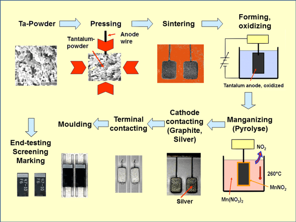
Figure 3. Manufacturing process of solid tantalum (MnO2) capacitors; source: Wikipedia
Polymer and Manganese Dioxide MnO2 Solid Tantalum Capacitors
Introduction
Cross-section schematics of typical SMD tantalum chip construction are shown in Figures 4. and 5.
Tantalum metal has a dielectric constant of approximately 27. The price for solid tantalums is relatively high due to mainly the high cost of the tantalum powder. The solid electrolyte theoretically has no limitations in operation and storage time. The capacitance range extends up to some thousand µF. The capacitors are characterized by a high CV product per volume unit, especially when high CV powders above 200k CV/g are introduced for low and above 80k CV/g for higher voltages.
The conventional solid electrolyte is MnO2. However, conductive polymer types are becoming increasingly popular due to their lower ESR and reduced ignition features. On the other hand, MnO2 types are more robust against thermo-mechanical stress and stable electrical parameters under high temperatures and highly humid environments. Thus, high reliability and extended operation lifetime applications still mainly use established reliability MnO2 types as the main tantalum solid capacitor technology.
Physically, the capacitor also has a high density. Thus, lead-mounted components permanently should be fixed mechanically against their substrate. This type requires large margins to the forming voltage, usually 2 to 4 times VR. Ratios above four are needed for automotive and other high-reliability applications, while a balance around two may be sufficient for consumer electronics. The higher ratio favours not only higher reliability but also better capacitance stability.
On the other hand, higher VF/VR ratios mean a correspondingly lower volumetric efficiency (capacitance is inversely proportional to the dielectric thickness). The maximum VR stops at 125 V DC for capacitors with polymer electrolytes and 100V DC for MnO2 types. However, derating rules are different. It is recommended to derate MnO2 types by 50% for current surge circuits (directly on battery or DC/DC input) and 20% for non-high surge existing applications (DC/DC output, timing, coupling/decoupling …). Tantalum polymer derating is recommended at 10% for up to 16V capacitors and 20% for >16V capacitors for all kinds of applications.
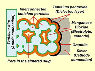
Figure 4. Explanation of tantalum MnO2 capacitor inner structure (not to scale); source: KEMET
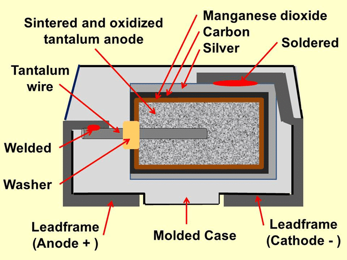
Figure 5. SMD tantalum MnO2 capacitors structure; source: KEMET
The capacitance stability is good (∆C/C ≤ ± 5%), and the tolerances range from (±5) ±10% to ±20%. The reverse voltage should, at a maximum of 85 °C, be limited to the most negligible value of the alternatives: 10 % of VR or 1V. Continuous reverse voltage operation is not recommended. However, small uneven spikes, such as diode overshoot voltage, are acceptable. Chip designs are becoming very common and well documented; some basic case sizes have been established with a functioning international standardisation. However, the market need and manufacturers’ feedback was faster thann standardization. There are several other case variants with different letter codes per manufacturing that may be very confusing in some cases – as the same letter from one manufacturer has different dimensions to the other.
For example,, AVX X case is a 1.5mm low profile variant of the standard D case 7343 chip (the AVX X case is equivalent to KEMET’s W case). However, KEMET X case is a taller 4.3mm variant of the classic D case 7343 part. (KEMET X case is equivalent to AVX E case).
The case size variants from manufacturers on the market is, so vast that they are now using nearly complete alphabet options and have begun to use also numbers or combinations of letters and numbers for different case size dimensions. The following table shows the standard few sizes of a series that has acquired international acceptance under the same letter code:
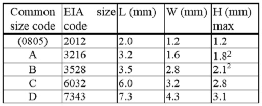
Table 2. Standardized SMD tantalum capacitors chip sizes.
