This article provides an in-depth exploration of these fundamental electromagnetic components: solenoids and transformers, detailing their structures, operating principles, types, and applications.
Transformers
A transformer is a device that transfers electric energy from one alternating-current circuit to one or more other circuits, either increasing (stepping up) or reducing (stepping down) the voltage. A transformer consists of at least two windings, with the winding turning NP on the primary side and NS on the secondary side.
For the sake of simplicity, we will look at an ideal transformer with a turn ratio of 1: 1.
In the first step, we will look at a transformer with an open secondary winding NS (Figure 1.). A UP voltage pulse is created at winding NP. Due to the inductance of the winding, this pulse generates a linearly progressive current IP.
The following applies:

transformer voltage pulse eq. [1]

induced voltage in the transformer by magnetic flux [2]
Winding NS also wraps around this magnetic flux. Changing the magnetic flux creates voltage
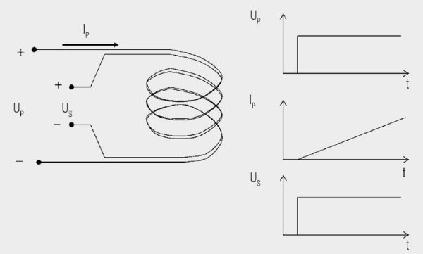
Figure 1. Principle of a transformer with zero loads. This ideal transformer is wound as a bifilar to ignore parasitic effects.
If you solve both equations after changing the voltage and then equating them, you will get the following for the voltage transformation expressed by eq. [3].
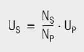
voltage transformation eq. [3]
Current does not flow in winding NS because the winding is open. If we now connect winding NS to a load resistor RL (Figure 2.), the voltage induced in NS generates a current flow through the load resistor:
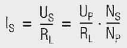
current through transformer eq. [4]
he primary current now consists of the transformed secondary current and the linearly progressive magnetization current already available without load.
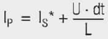
transformer primary current eq. [5]

Figure 1. Principle of a transformer with zero loads. This ideal transformer is wound as a bifilar to ignore parasitic effects.
Figure 2. The same transformer as in Figure 1. but with a load
As no power can be generated, the transforming power is the same as the primary power put into the system. If the magnetization current is disregarded, the following applies:

Currents are thus in the reversed direction as voltage. The following also applies:

Resistances are thus transformed with the transformation ratio squared. This also applies to inductances, capacitances, and impedances. So the magnetizing current is not transferred to the secondary side. It is required to generate the magnetic field. The aim of the transformer design must therefore be to keep the magnetizing current as small as possible.
There are two possibilities here:
- Insertion of a highly absorbent core to increase the primary inductance. This causes the magnetizing current to rise less steeply and is, therefore, smaller (Figure 3.).

Figure 3. Magnetizing current of a transformer with and without a highly permeable core
Parasitic effects
In reality, other factors affect the behavior of transformers. The most important ones are:
- Leakage inductance
- Coupling capacitance (capacitance between windings)
- Winding capacitance (capacitance within a winding
- Shorter voltage pulses with higher frequencies are generated as the current rise stops at the voltage pulse’s end and starts again at the original point for the next pulse (Figure 4.).

Figure 4. Magnetizing current for a transformer at different driving frequencies

Figure 5. Long solenoid concentric coil
Leakage inductance
Looking at two windings, we see that the entire flux is not coupled to the other winding. A part of the magnetic field’s streamlines closes outside the other winding. This part of the inductance is called “leakage inductance.” To minimize leakage inductance, you must know the parameters that influence it.
If you look at a long concentric coil (Figure 5.), its inductance results from:
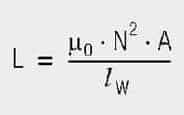
concentric coil inductance eq. [5]
lW Length of the coil
N Winding turns
A Cross section of the coil
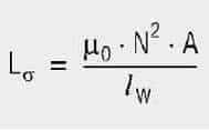
If a second winding is wound on top of it (Figure 6.), the leakage inductance results from eq. [6]
leakage inductance on second winding [6]
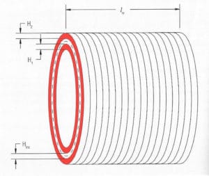
Figure 6. Long solenoid concentric coil with second winding
Where A here is the surface between the two windings. It can be calculated using:

the surface between two windings eq. [7]
MLT Mean length of turn
Hins Distance between the windings (isolation)
H1, H2 Winding height of windings 1 and 2
Coupling Capacitance
You can picture the coupling capacitance between the two windings as a plate capacitor between the two windings. From this, you can reduce this capacitance by increasing the distance or reducing the surface. Both directly increase leakage inductance.
Winding Capacitance
Each winding builds up winding capacitance because they are isolated from each other and rest on different potentials. This capacitance increases with the number of layers required within a winding. It can be reduced using various winding technologies, e.g., Z-wind (wire is returned after each layer).
Solenoids
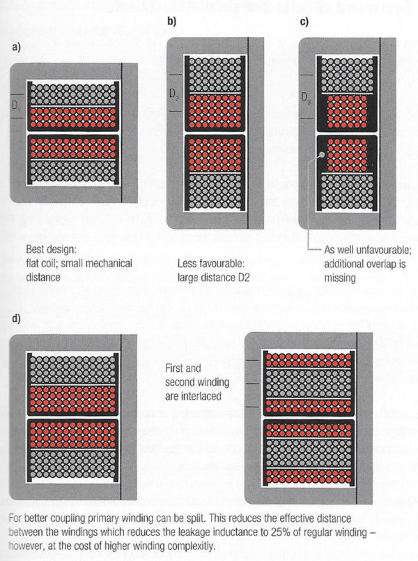
Figure 7. Different transformer winding structures
Working Principle
A solenoid works on electromagnetism and electromagnetic force. It consists of a round cylindrical coil with several wires turns and a metal rod inside the coil that is free to move. When an electric current is provided to the coil, a magnetic field is generated, due to which the metal core or rod inside the coil gets attracted due to the direction where the magnetic flux is high. This electromagnetic effect in a solenoid enables any connected plunger or armature to move as per our needs.
To increase the magnetic force produced in a solenoid coil, we will have to increase the number of turns, N, and the current, I.
Types Of Solenoid
AC Laminated Solenoid
It has a very high initial attracting force and a short closing time. It is made with laminated metal or insulated thin sheets that are individually, assembled.
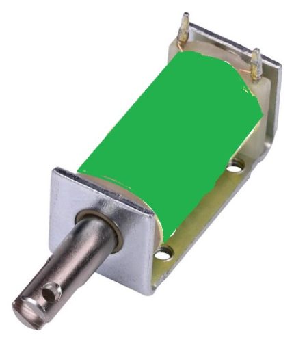
DC-C Frame Solenoid
As its name states, this solenoid is constructed with a letter ‘C’ like frame cover around the coil. This type is widely used in gaming machines.
DC-C Frame Solenoid
DC-D Frame Solenoid
As its name says, this solenoid has a coil covered by two ‘D’ frames on two sides. These types are generally used in AC power applications.
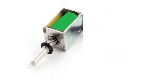
DC-D Frame Solenoid
Linear Solenoid
This solenoid type has a freely movable steel or iron rod called a plunger inside a round cylindrical-shaped coil. Depending on the current applied, the iron rod can freely move in or out of the cylindrical coil.
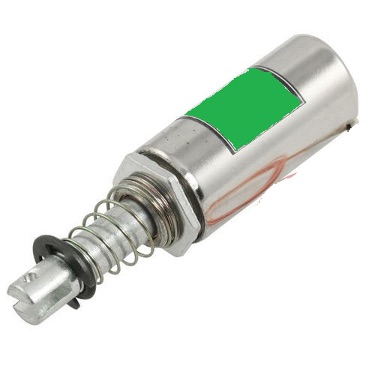
Linear Solenoid
Applications
Solenoid Valve
The solenoid valve is a simple device in which a solenoid is used to control and regulate fluid flow. It has a coil with a free movable plunger or an iron rod with a spring inside. When we energize the coil, the plunger moves from its position due to magnetic attraction, and when we cut the power to the coil, the plunger returns to its original position with the help of a spring. As soon as the plunger comes in the path of the flowing fluid, its flow stops.
Solenoid Lock
Here we use the movement of the solenoid plunger for the locking and unlocking mechanism. These solenoid locks are widely used in electronic and biometric password-based locks. It consists of a strong metal plunger that can move. When the coil gets magnetized due to an electric field, the plunger moves to perform the lock and unlock mechanism.
The leakage inductance is thus independent of core material and air gap. To minimize leakage inductance, you must either increase the length of the coil (broad windings) or reduce the distance between the windings (e.g., bifilar wind).
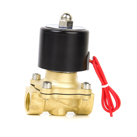
Linear Solenoid
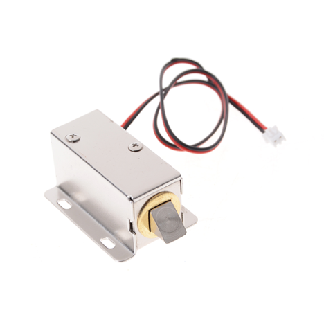
Solenoid Lock
Figure 7. shows various more or less ideal winding constructions. With existing geometry, the most commonly used means is a sandwich construction (Figure 7.d), in which the secondary winding is wound between the primary winding divided into two halves. This doubles the length of the winding.
Resources: EPCI Blog

