This article is the third part of a complete installment on the in-depth analysis of capacitor losses. It focuses on ESR (Equivalent Series Resistance), Dissipation Factor (DF or Tanδ), and the Quality Factor (Q). It explains how losses vary with frequency and the use of series or parallel equivalent circuits for analysis.
The article is divided into stages:
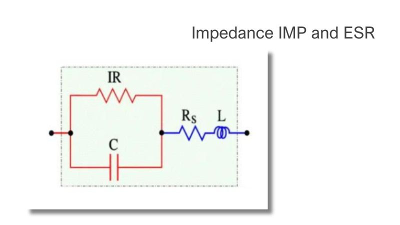
- Impedance IMP and ESR
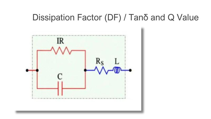
- Dissipation Factor (DF) / Tanδ and Q Value
- Series or Parallel? Cs, Rs or Cp, Rp? ESR or DF?
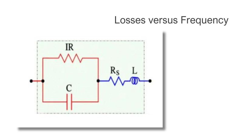
- Losses versus Frequency
Series or Parallel? Cs, Rs or Cp, Rp? ESR or DF?
An impedance analyzer can measure capacitance in parallel or in series. The capacitor’s capacitance value will determine the best-fit circuit model.
When C is small, and the impedance is high, the parallel impedance between C and Rp will become significantly higher than Rs. Thus, the meter setting for measuring capacitance should be Cp. When C is large and the impedance is small, the parallel impedance for C and Rp is not as significant. Therefore, Cs should be used for the meter set to measure capacitance.
A good rule of thumb for selecting the impedance setting is to use Cp for capacitor impedance values greater than 10kΩ and Cs for less than 10Ω.
Equivalent circuits ESR or DF?
Another practical outcome is considering what parameter better describes losses in a capacitor – ESR or DF? From the pure physics point of view, it does not matter, as together with a second parameter (capacitance or impedance), both parameters describe the same stage of the capacitor. While ESR is only information about real losses, DF combines information about real losses and reactive losses (but we need the second parameter to describe the exact capacitor stage).
The same is true about ESR/DF frequency dependence. It does not matter if I use ESR or DF characterization for description at low or high frequencies from basic physics. However, the industry convention is to use DF for low-frequency (120Hz or 1kHz) characterization, where dielectric losses dominate, and ESR for higher-frequency (100kHz) behaviour, where resistive connection losses are the main part of the losses. You can find DF and ESR values in manufacturer datasheets concerning those frequencies.
Case study: you can hear people from the industry saying: “that capacitor has a high DF” that means that the capacitor has a high loss in the lower frequency zone (120/1kHz) that could indicate some issue with dielectric material (impurities, delamination …). and of course, ESR at 120Hz/1kHz will also be high. The same is about ESR – when someone says: “ESR of the capacitor is a problem,” he/she usually means a reference to the standard measurement frequency 100kHz indicating problems with resistive losses (inter-connection issues, bad welds, etc.) … and of course, DF at 100kHz would also be high.
Continue reading at: 4. Losses versus Frequency
Related Articles
Impedance IMP and ESR
Dissipation Factor (DF) / Tanδ and Q Value