This article is the third part of a complete installment on the basic key parameter of capacitors—capacitance—and its relations. It is divided in 4 chapters:
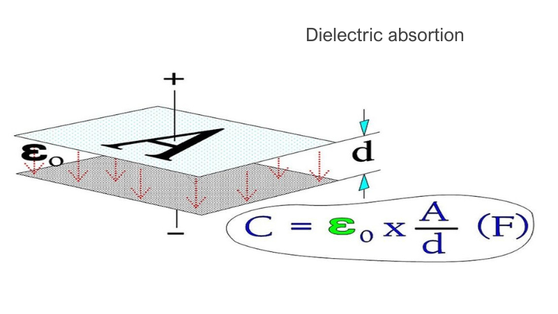
The section about dipoles and of dielectric absorption is of vital importance for the understanding of the practical capacitor. All materials contain some dipoles, i.e. electrically polar elements. When they are subjected to an electric field, it creates a torsional moment that, depending on the field strength, will tend to align them in this field. These torsional moments can be divided into four groups. Those which are caused by
- electron movements in atoms and molecules,
- atom movements in symmetrical molecules,
- atom movements in unsymmetrical molecules and
- charge accumulations on interfaces between different materials in the dielectric.
As long as the capacitor is not biased, the dipoles have a random orientation without any resulting pole. It may, in principle, looks like Figure 8.

Figure 8. Dipole orientation in an unbiased dielectric.

Figure 9. Perfectly-aligned dipole chains.
The electric field strength (the number of imaginary field lines which would have formed in a vacuum) has been reduced with the number of established dipole chains. Every dipole chain binds in the interface towards, for example, the positive electrode a + charge, and the number of free charge carriers in the electrode has been reduced to a corresponding degree. Thus, after the alignment time of the dipoles, the electrode can receive as many new free charge carriers as those the dipole chains have bound without increasing the electric field strength (or the voltage) above that of the starting point. This means a corresponding increase in capacitance. If we call this polarizability, the number of bound charges q and the number of charges at the starting point Q, it can be shown that.

……………………. [7]
The function of a versus frequency is shown in Figure 11. below.
Because εr depending on the dielectric material, varies approximately between two and many thousands, we realize the enormous significance of the material dipoles and the polarizability.
Frequency dependence of capacitance
The velocity with which a dipole reacts for an applied electric field is called its relaxation time. These relaxation times range from 10-17 s for the electron-dependent dipoles to several hours for the large molecular complexes. That means that the fastest dipoles keep up with all practical frequencies while the slower, to a varying degree, need time to contribute with capacitance-increasing dipole chains. The phenomenon can be described as a basic capacitor combined with several additional capacitor elements hidden in resistive circuits with shorter or longer time constants (Figure 10.).

Figure 10. Dipole categories in a capacitor.
An example of the frequency range that different types of dipoles contribute to is shown in Figure 11.
- αe = dipole effect from electron movements;
- αa = dipole effect from atom movements in symmetrical dipoles;
- αd = dipole effect from atom movements in unsymmetrical molecules;
- αi = interface-dependent dipoles
- αe = dipole effect from electron movements;
- αa = dipole effect from atom movements in symmetrical dipoles;
- αd = dipole effect from atom movements in unsymmetrical molecules;
- αi = interface dependent dipoles

Figure 11. A typical example of schematic variance of polarizability in a solid material with frequency.
Source: EPCI
Related Articles
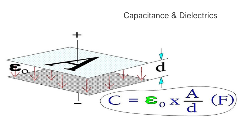
Capacitance & Dielectrics
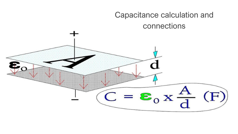
Capacitance calculation and connections