This article is the last part of a complete installment on the in-depth analysis of capacitor losses. It explores how losses and frequency are interrelated in polar and non-polar dielectric materials.
The complete analysis is divided into 4 stages:
Losses versus Frequency
Just in the range where the reaction time of the dipoles and the frequency period coincide, a kind of resonance occurs which causes the dipole types to react with a loss peak (Figure 9).
Observe that Figure 9. deals with dipole losses, nothing else. Other dielectric materials have no molecular dipoles. They are called non-polar, while the others are called polar. This has nothing to do with the polarity dependence of electrolytes.
The sum of losses in a polar and a non-polar capacitor may look like the ones in Figure 10.

Figure 9. Dipole losses versus frequency
Figure 9. illustrates the behavior of different dielectric dipoles when they are affected by an alternating field. They will oscillate at the same frequency as the fields if allowed by their reaction time. Every rotary motion requires energy, and the executed work produces heat. The most inert dipoles will react to very low frequencies and contribute to the losses. But as the frequency increases, the different types of dipoles will not be able to respond quickly enough, one after another, as shown in the figure.
We shall remember that dielectric losses (material permittivity) may be frequency dependent. As per the basic capacitance calculation, it is the only parameter responsible for capacitor frequency dependence in the ideal capacitor (considering the surface area of electrodes and thickness of dielectric stable). The real capacitor may have an additional RLC ladder structure that limits its resonance and maximum operating frequency.

Figure 10. Total losses versus frequency in a polar and non-polar dielectric material
Related Articles
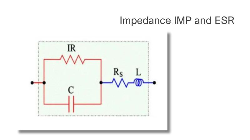
Impedance IMP and ESR
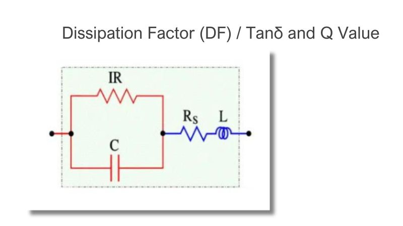
Dissipation Factor (DF) / Tanδ and Q Value