This article is the first part of a complete installment on the basic key parameter of capacitors—capacitance—and its relations. It is divided in 4 chapters:
- Capacitance & Dielectrics
- Capacitance calculation and connections
- Dipoles
- Dielectric absortion
Capacitance is determined by, among other things, the characteristics of the dielectric material. International standards speak of the Dielectric Constant or permittivity, designated by the symbol ε.
Description
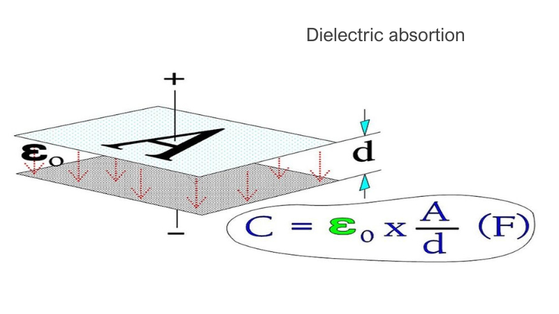
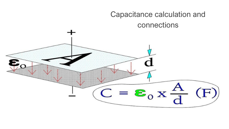
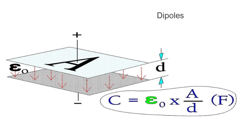
A capacitor serves as a reservoir for electric charges. The size of the ”reservoir” is called capacitance and is expressed in the quantity F(arad) or As/V. The principle Figure 1. shows how the capacitance is directly proportional to the active area A and the dielectric constant and inversely proportional to the distance between the electrodes. The formula in the figure applies to vacuum and air.

Figure 1. The principle of capacitance, C.
A = area (m2),
d = distance between electrodes (m),
ε0 = dielectric constant for vacuum (≈air) = 1×10⁻⁹/36π.
If the electric charge quantity of the capacitor is designated with Q (As), then the general formula 1 is valid.

……………………………… [1]

Figure 2. Dielectric with its constant
If we now insert an insulator material between the electrodes, as shown in Figure 2., the formula in figures 1. and 2. gets the following general expression:

………………………………. [2]
εr is a relative number – the relative dielectric constant – which tells us how many times the capacitance is magnified when we exchange the air gap between the electrodes with different dielectric materials. That’s the relative dielectric constant εr which is given in technical tables and catalogs.
The table below shows the dielectric constant of the most common materials.

Table 1. Dielectric constants of most common insulating materials
Capacitive Reactance
Suppose we change the polarity in Figure 2. by applying an AC voltage over the capacitor. In that case, it will cause a certain resistance in the circuit, a so-called capacitive reactance, XC, expressed in ohms.
The reactance is inversely proportional to frequency according to the formula.

…………………….. [3]
- ω = 2 x π x f,
- f = frequency in Hz,
- C = capacitance in F.
Measure of miniaturization
The desired miniaturization of different capacitor types can be expressed in different ways. The smallest rated voltage for electrostatic capacitors often is more than enough for the application. Hence we usually disregard the voltage and compare the various types using their maximum possible C/V rate, which means capacitance C per unit volume V (d * A in Figure 1). According to the Formula [2] we get C/V = ε0 * εr * A/(d * A * d) = ε0 * εr /d2. The rate C/V will be at maximum for dmin, i.e., for VRmin.
In electrolytic capacitors, the rated voltage plays a greater role because it can also be adapted to very low working voltages. Here the capacitors are grouped according to their charge quantity, that is to CR*VR. We refer to the CV product.
Source: EPCI
Related Articles
Capacitance calculation and connections
Dipoles