This article is the second part of a complete installment on the basic key parameter of capacitors—capacitance—and its relations. It is divided in 4 chapters:
- Capacitance & Dielectrics
- Capacitance calculation and connections
- Dipoles
- Dielectric absortion
If we connect capacitors in parallel as shown in Figure 3. the active area (and hence the capacitance) increases with all additional capacitor elements.
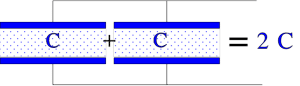
Figure 3. Principle figure of the total capacitance when the elements are connected in parallel.
The formula for the total capacitance of connections in parallel:

……………. [4]
Figure 4. shows, in principle, how connection in series increases the dielectric thickness without changing the charge quantity. The capacitance decreases proportionally to the increase in dielectric thickness.

Figure 4. The principle of series connection
The figure shows a simplified picture of a series connection with two equally large part capacitors. If we instead choose capacitor elements of unequal size, the charge quantities on the different electrodes still will be equally large, i.e. Q = CV = C1V1 = C2V2 = C3V3; Q/C = V; Q/C1 = V1; Q/C2 = V2; Q/C3 = V3…But V1 + V2 + V3 +….= V. This gives us in general, the total capacitance for Series connection:

……………. [5]
Mixed dielectrics
So-called mixed dielectrics have become more and more common. They consist of different film materials in the same capacitor. For example, by winding a capacitor with a paper and a polyester film dielectric, we combine the excellent self-healing properties of paper and the relatively high insulation resistance of polyester. In principle, it’s still a question of two capacitor elements in a series connection with the same area and the dielectric thickness d1 + d2. Then the relation we depicted above is valid: Q = VC = V1C1 = V2C2; V1 x ε1 x A/d1 = V2 x ε2 x A/d2; if we denounce the electric field intensity E we then obtain ε1 x E1 = ε2 x E2, or in general
ε1 x E1 = ε2 x E2 = ε3 x E3 = ……………………… [6]
Other non-plate and various geometry capacitance calculations
The capacitance calculation by equation [2], illustrated in figure 2, is based on plane capacitor type. However, many other capacitor construction types and geometries are on the market. See the theoretical capacitance value calculation for some of the other geometries as well as mixed dielectric situations below:

Figure 5. Capacitance calculation of various geometries and structures
Capacitance standardized values and tolerance
Following international standards EIA/IEC 62, capacitance values and tolerances are standardized as follows:
E Range
Capacitance is following standardized “E ranges” defined per logarithmic steps such as E3, E6 … E24, and E48 steps.
Naturally, the selected E-range is also linked to the tolerance field – not to overlap with the next capacitance tolerance range – see below.

Figure 6. E24 and E48 capacitance standard range example

Figure 7. E6 capacitance tolerance field example
Specific capacitor technologies’ E range is driven by its capability to produce reproducible and tight tolerance capacitance values in mass production. You can find the relevant capacitance values and tolerance ranges defined in manufacturers’ catalogs.

Table 2. EIA/IEC 62 tolerance field code
Source: EPCI
Related Articles
Capacitance & Dielectrics
Dipoles