160 ILLUMINATED PHOTODIODES
Development of a complex setup capable of simultaneously measuring 20 solar sensors under homogeneous incident light
During the last decades, continuous technology improvement has allowed the development of increasingly smaller and cheaper satellites. Different private companies figured out this fact and started to think about the possibilities of having their satellite constellation. One of the goals of these constellations is to provide high-quality internet services via satellite to any point of the globe. However, achieving this target requires hundreds or even thousands of satellites operating simultaneously. This situation pushes the space market companies to offer innovative solutions to deal with the magnitude of components and devices verifications required for this kind of macro-projects.
Alter Technology has participated in these new space projects in different ways. One of our collaborations was developing a complex setup capable of simultaneously measuring 20 solar sensors under homogeneous incident light during thermal cycles testing. The Device under test (solar sensor) was composed of eight photodiodes, and with them, the sensor was capable of knowing both the direction of the incident light and its intensity.
The complexity of the setup performed was the routing and measurement of such quantity of signals (180) and the generation of a homogeneous illumination for the sensors during the thermal cycling.
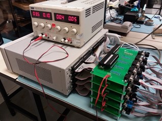
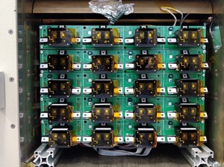
To solve the first obstacle, a PCB (Sensors PCB) was designed, which allowed the fixation of up to 4 sensors and the controlled routing of their photodiodes’ signals. Each PCB includes the possibility of adding up to 4 control photodiodes and four control RTD (PT-100) close to the sensors. Besides, to measure the drop voltage of each photodiode, we use resistance in series with each of them. Another PCB (Resistors PCB) was designed to place all the resistances required. These Resistors PCBs are placed outside the climatic chamber to avoid the thermal influence in the resistance measurement.
Summing up, each Sensor’s PCB is routed to a Resistor’s PCB and finally to a Datalogger. The following pictures illustrate the above description:

Electrical connection check between the Sensors PCB and the Resistors PCB

Power source, datalogger and Resistors PCB

Example of a lot of sensors placed inside the climatic chamber and ready to test.
