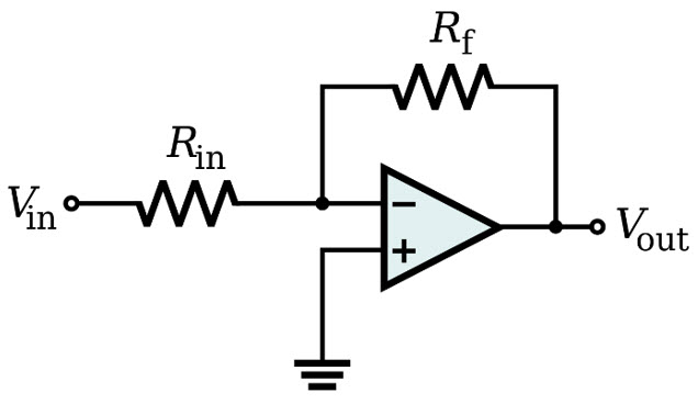
Operational Amplifiers (OpAmp) are widely used components on any electronic equipment nowadays, and of course, this includes Space applications. However, the particularities of this business make that not any part is suitable for this market segment.
Anyone looking at one of the main manufacturers of space parts website can notice that the offer of OpAmps specifically released for Space applications is quite low compared to the total offer of the manufacturer. Indeed, Space parts are often honoured with a specific category on the website. Therefore, the question is: what should I consider for selecting an OpAmp to be used in Space equipment?
The first step is to define characteristics you need for your OpAmp, independently on the environment of use. These are Gain (dB), Typical Gain Bandwith Product (MHz), Common mode rejection ratio (dB), the number of circuits included in the part (Mono, Dual, Quad…), and Input and Output Voltages and Currents, etc

Here below, you can find a brief description of these parameters:
Gain Bandwith Product [Typ] (MHz): It is the product of the amplifier’s bandwidth and the gain at which the bandwidth is measured. This value determines the maximum benefit that can be extracted from the device for a given frequency (or bandwidth) and vice versa.
Gain (dB): Measures the increase in the amplitude between output and input voltage.
Number of Circuits: Number of Operational Amplifiers inside the part.
Input Bias Current [Max]: Ideally, no current flows into the input terminals of an OpAmp. However, there exist two input bias currents into the input terminals, which produce voltages that increase output errors in the circuit.
Output Current [Max]: It is the current provided in the output of the component
Input Offset Voltage [Max]: It is the differential DC voltage required between the inputs to make the output voltage equal to 0. Ideally, a voltage difference between the differential inputs of an OpAmp of 0V would result in a 0V output. However, in practice, it is not so, but output voltage reaches 0V at a particular value of the voltage difference between the differential inputs of the OpAmp.
Common Mode Rejection Ratio [Min]: This is the ratio between the common-mode gain to the differential-mode gain. It serves as an indication of the importance of the common-mode signal in the output, or the ability of the OpAmp to discard common-mode messages.
Slew Rate [Min] (V/us): Rate of change of the output voltage caused by a difference in the input voltage. This parameter is critical for some applications to know how fast the output can accommodate a change in the input. Also, its maximum value limits the response of the OpAmp.
The second step is to find an OpAmp with the electrical characteristics needed suitable for use in the Space Environment. There are 5 main topics to be considered:
Operating Temperature:
The part must be guaranteed to perform correctly in the Military Temperature Range, this is [-55º, +125]ºC. Otherwise, qualification/testing to assure functionality over this range must be performed.
Qualification/Testing:
Depending on the class of the project, the operational amplifier selected for a space mission will need to have a certain quality level, and a specific screening and Technology Conformance Inspection flow will be required.
While for a Class 1 project, an OpAmp qualified under MIL-PRF-38535 would be the preferred option, the use of a COTS part with additional testing would be a possible alternative for another kind of projects as low-orbit projects with a short mission time, where Product Assurance requirements may not be as demanding as in the first case.
For the selection and general Product Assurance requirements for Space Projects, ECSS-Q-ST-60C Rev2 will serve as general guidance. If a COTS part is selected, product assurance requirements depending on the Project’s class can be found in ECSS-Q-ST-60-13C.
Materials / Package:
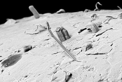
Due to Space conditions, OpAmps used for this market must comply with certain material restrictions, as shown in ECSS-Q-ST-60C Rev2. Notably, parts shall not contain Pure Tin (either as an underplate or as a final finish, both internally and externally) to avoid the risk of suffering from tin whiskers. In case this is not possible, mitigation techniques such as retaining shall be considered.
On the other hands, materials can suffer from outgassing on vacuum conditions at high temperatures. Therefore, it must be confirmed that the materials that are used to manufacture the selected OpAmp are compliant to acceptable limits for applications as per ECSS‐Q‐ST‐70‐02C.

Radiation Sensitivity:
Effects of different types of radiation such Ionizing Dose, Non-Ionizing Dose and Heavy Ions on the selected OpAmp shall be considered. As a first approach, radiation hardness guaranteed parts shall be selected. If there is not any Rad-Hard guaranteed part available that satisfies our needs, a Radiation Verification Testing by ECSS-Q-ST-60-15C shall be performed on the lot procured.
Most OpAmps qualified for space applications are manufactured using Bipolar or BiCMOS technology; therefore, effects of LDR (Low Dose Rate) TID (Total Ionizing Dose) shall be considered. In terms of sensitivity to Single Event Effects (SEE), Operational Amplifiers are sensitive to SEL (Single Event Latch-up) if the technology used on the part is BiCMOS, but immune if the technology is pure Bipolar. Also, all OpAmps are considered sensitive to SET (Single Event Transients) independently of their fabrication technology.
Derating:
Derating consists of designing the operational range of the component on our specific application so the part performs at a significantly reduced level of stress to increase reliability and to ensure useful life and design margins. According to ECSS-Q-ST-30-11C Rev1, derating must be applied to some parameters of Microcircuits to be used in space projects. In the case of OpAmps, these parameters are supply voltage, input voltage, output current, maximum junction temperature and transients.
If these topics have been considered, the correct selection of the appropriate OpAmp for our application is closer than ever.
Download here below, all the relevant documents:
