
Variable resistors are electromechanical components and, therefore, expose not only to the weaknesses of fixed resistors but also to all the failure possibilities of electromechanics. Thus the reliability is comparatively poor.
The total resistance seldom is critical and usually follows the European E3 series or 1-2-5-10 (USA).
Potentiometer Basic Concepts
Introduction
A third one is connected to a sliding contact or Wiper between the two fixed terminals. Because the direction of motion of the sliding contact is hidden in encapsulated types, the fixed terminals usually are marked with
- CW, i.e., clockwise, and
- CCW stands for counterclockwise.
With the slider positioned in either of the two endpoints, we measure the Rated resistance, Rtot, between the fixed terminals of the potentiometer. In Figure 1, we also have indicated the rest or End resistance, ER, that in wire-wound potentiometers is measured between terminals (2) and (1) or (2) and (3) when the Wiper is positioned in the corresponding endpoint where integral stops prevent further movement. In non-wire wounds, the shaft shall be placed at either of the theoretical endpoints, i.e., at the ends of the academic electrical travel (Figure 4). Sometimes, the end resistance, ER, is expressed in % of Rtot. Precision wire-wound potentiometers have terminations like the one in Figure 2.
If we measure the rest resistance, we also get an extra contribution from the futile part of the resistance track (position B in the figure). If we move the Wiper to position A, the resistance will drop to a minimum, the so-called Minimum resistance, MR. Instead of ER, the End voltage, EV, is specified for non-wire-wound precision potentiometers.
According to the Variable Resistive Components Institute (VRCI) industry standard, measurement shall be done between the Wiper and an endpoint. The shaft is then positioned at the theoretical endpoint (non-wirewound) or the endpoint (wire-wound). The theoretical endpoint is represented by position B1 in Figure 3. The endpoints of a wire-wound potentiometer are defined by the start of actual electrical travel in Figure 1. The end voltage is expressed in per cent of the input voltage E.
If we, as proposed, measure position B, the result will be the same as that of position A. The current through the DVM is assumed to be negligible.
The Minimum voltage MV is the smallest or lowest voltage between the wiper terminal and an end terminal when the shaft is positioned near the corresponding end of electrical continuity travel (Position A in Figure 3).
Actual electrical travel applies to wire-wound potentiometers only and concerns the total travel between endpoints, as shown in Figure 4.
At that point of the shaft travel, where we start observing the first significant changes in the output voltage, Type 2 potentiometers and trimmers sometimes have a definition of the Effective minimum resistance. Compared to the End Resistance, ER is approximately ten times higher, for example, 2%, when the ER is specified to 0.2%.
The Total mechanical travel is determined by the total travel of the shaft between integral stops. If there are no stops (as in non-wire-wound servo potentiometers), the motorised travel is continuous. Thus, the mechanical journey is 360°.
That part of the travel where we have a continuous electrical connection between the wiper and terminals is called Electrical continuity travel. In wire-wound potentiometers, it coincides with the total mechanical travel.
The corresponding output ratio is the Index point, IP at a specified shaft position. Usually, IP is positioned at approximately 50% of the maximum output ratio. It is used to establish a shaft position reference, for example, when specifying the Theoretical electrical travel that usually is centred between the endpoints of the actual electrical journey, Figure 4. Suppose now that the IP is defined at shaft travel of 170°. The theoretical electrical travel then will range between 0 and 340°.
The Insulation resistance, IR, is measured with DC between the connected terminals and all other electrically conductive parts like a shaft, metal housing, mounting details, etc. IR should be at least 1000 MΩ.
Cycle. In potentiometer contexts, we meet the expression cycle, which means shaft travel from one end point to the other and back to the starting point.
Rotational life. The specified maximum number of shaft revolutions a potentiometer shall be able to stand with preserved resistance stability is called rotational life.
Potentiometer or Encoder – What is the difference?
Potentiometer or Rheostat
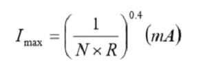
Figure 5. shows the principle functions of a potentiometer and a rheostat. The current through the rheostat may never exceed Imax in the formula:
Conformity

Figure 1. Definition of electrical and mechanical travel in potentiometers

Figure 2. End resistance and minimum resistance of potentiometers.

Figure 3. Potentiometer end and minimum voltage.

Figure 4. Schematic sketch of different potentiometer travels.

Figure 5. Potentiometer and rheostat connections.

This formula applies also to the potentiometer.
Potentiometer Linearity
Introduction

Figure 6. Schematic of a potentiometer.

Figure 7. Potentiometer output voltage versus wiper travel.
If we compare Figure 6. with 7. we may imagine how the terminal metallization acts like a landing strip for the output voltage (the plane parts at the beginning and the end of the actual electrical travel).
Independent linearity
Specification of the independent linearity is used, for example, on such potentiometers where the user wants to adjust the gradient of the output voltage. It is done by means of built-in resistor elements connected to the potentiometer track.

Figure 8. Potentiometer independent linearity – wire wound

Figure 9. Potentiometer independent linearity – non-wirewound
Zero-based linearity

Figure 10. Potentiometer zero-based linearity – wire-wound only.

Figure 11. Potentiometer terminal-based linearity. Wirewound only.
Taps
Certain applications require additional terminals. These are called taps and exist in both wire wound and non-wirewound potentiometers. In the latter, they have either of two functions: Current taps and voltage divider taps. The former ranges over the width of the whole resistance track and disrupts the linearity. The latter are located at the outermost edge of the track and don’t influence the linearity.
Gang potentiometers
Sometimes several potentiometer elements called cups are coupled together on a common shaft. The assembly is called a gang. The technique requires some definitions.
Phasing point
To meet the requirement of simultaneous conformity or tracking, gang cups are phased together at a common reference position of the shaft. For linear potentiometers, that shaft position is usually chosen where the output ratio e/E of the electrical elements is approximately 50%.
Tracking
Simultaneous conformity
Loading Error
Figure 13. Potentiometer tracking error = difference in output ratio Δe

Figure 14. Potentiometer loading error.
Resolution
From MIL-R-39023, we quote the definition of resolution: ”A measure of the sensitivity to which the output ratio of the potentiometer may be set”. The same MIL standard also defines voltage resolution as “The maximum incremental change in output ratio with shaft travel in one direction in any specified portion of the resistance element” (applicable to wire-wound only). The resolution is expressed in per cent of the input voltage E. The higher resolution, the lower percentage.
Descriptions of non-wirewound potentiometers sometimes discuss “Infinite Resolution”. More literally, it should be written in “infinitely high resolution”. The resolution of a wire-wound potentiometer with N number of turns may be approximated to the reciprocal 1/N.
Adjustability
The resolution of trim potentiometers has the name adjustability, which means setting accuracy or suitability. It is stated in per cent of the total applied voltage E (or of Rtot) and thus measures the accuracy with which a desired voltage (or resistance) may be set.
Potentiometer noise
CRV Contact Resistance Variation
CRV stands for Contact Resistance Variation. Before we discuss this concept, let us begin with Contact Resistance in general. The contact between the wiper and track has a certain resistance, the value of which depends on the contact pressure, the track material and its nature, the current through the wiper, etc. The Contact Resistance (CR) increases, for example, exponentially with decreasing wiper current somewhere below 1 to 0.1 mA. The more metal in the resistance element, the less pronounced the phenomenon. Figure 15. shows in principle the CR of a cermet potentiometer, but the curve could equally well be applied to a wire-wound potentiometer.
In addition, the wiper current varies from point to point along the travel track. In addition to the contact resistance, there is in non-wire wounds also a certain track material resistance (Figure 16.).
We can call the sum of all these static resistances Contact Resistance, CR. In the endpoints they are part of the end resistance ER respectively, the minimum resistance MR. When the shaft then is moved over the track, arbitrary resistance changes or dynamic Contact Resistance Variations, CRV, occur that in principle may look like the record shown in Figure 17.

Figure 15. Contact Resistance (CR) versus wiper current in a cermet potentiometer.

Figure 16. Potentiometer resistance parts in the contact function of the wiper. Non-wire wounds.

Figure 17. Schematic of contact resistances in a potentiometer.
The figure applies in principle to both wirewound and non-wirewound potentiometers. Wirewounds have a fixed contact resistance (CR) that usually lies considerably below 1 ohm. Non-wire-wound CRs are in the ohms range (See explanatory Figure 16.).
ENR Equivalent Noise Resistance
For wirewound potentiometers the Equivalent Noise Resistance, ENR, is specified. Usually, it is measured according to the setup in Figure 18. The current generator feeds 1 mA through the wiper. The voltage drop across the contact then may be graded directly in ohms (1 mV corresponds to 1 ohm).

Figure 18. Test circuit for determination of the ENR in wirewound potentiometers according to MIL-R12934.
In conclusion: For mutual comparisons between potentiometer types the above mentioned specification is good. ENR information from application conditions, however, may require additional measurements.
Output Smoothness
Output Smoothness means the maximum instantaneous variation of the output voltage compared to the ideal output. This parameter is applicable to non-wirewound precision potentiometers only. The high resistivity of the track material and the geometry of the wiper contribute to a considerably higher contact resistance (CR) than the one in wirewounds. There would be considerable power generated in the CR if we used the test equipment for ENR in Figure 18. Instead the test circuit in Figure 19. is used.

Figure 19. Determination of potentiometer Output Smoothness according to MIL-R-39023.

Figure 20. Definition of potentiometer Output Smoothness.
Summary of output voltage errors
The different types of output voltage errors we have dealt with may be divided into static errors (deviations from the ideal output ratio) and dynamic ones (ENR, CRV and Output Smoothness). The latter is superimposed on the static ones, as shown in the following schematic.

Figure 21. Potentiometer static and dynamic output voltage errors.
The following formalized figures indicate the principal methods for determining mechanical properties. Different standards may state deviating forces and measures. US military specifications state, for example, ½ pound instead of 2 N and the distances are stated in inches (25.4 mm). The circle with a pointer symbol refers to a dial indicator for recording of mechanical movement. The figures are designed to be fully descriptive. Further detailed instructions have to be found in the standard in question.


Figure 22.-26. Potentiometer mechanical configuration from left: Shaft End Play; Runout; End Play; Lateral Runout; Pilot Diameter Runout
Backlash
If we turn the shaft in one direction until the output voltage has attained a specified value that we call e1 at a travel angle Θ = α1 and continue the movement a little before we turn back, we have to pass α1 a certain way before we attain e = e1. This will happen at a travel angle Θ = α2 and depends on mechanical play in the wiper system. Backlash is defined as the maximum difference between α1 and α2 and thus is expressed in degrees. The case is illustrated in Figure 27. and describes a mechanical hysteresis.

Figure 27. Backlash or wiper play = (α1-α2)°.
Potentiometer Type 2
Power potentiometers
The sliding contact of the wiper sometimes consists of silver. If there are sulfur compounds in the air, for example, from oil incineration plants, silver sulfides are formed on the sliding contact. If frequently recurrent adjustments do not wear off them, the next change of position will cause ESR values to go towards open circuit modes. A typical example of a power potentiometer is shown in Figure 28

Figure 28. Wirewound power potentiometer.
Panel mount potentiometers Type 2
The most simple carbon potentiometers have a sprayed and dried carbon compound on bakelite paper. After a number of cycles, they will meet with contact disturbance (noise) due to worn grooves in the track and wear debris around the wiper. The best rotational life is with the conductive plastic potentiometer. Due to the metal particles in the cermet, it develops an abrasive action that wears on the wiper. Therefore the track is often lubricated with a grease of some kind which reduces the wear.

Figure 29. Example of a bushing mount potentiometer. Manufacture Vishay Sfernice.
A phenomenon that threatens components with cavities if they are subjected to temperature changes in humid environments is the so-called pumping effect. An insufficiently sealed potentiometer with large holes inside the housing is particularly subject to this phenomenon. If moist air in the cavities is cooled, the water vapour condenses and creates a negative pressure at the subsequent temperature rise.
New humid air is sucked in, etc. Instead of having such a half-tight potentiometer, a hole in the bottom would be better, so condensed water could run out…Thus, use qualitatively sealed potentiometers if the environment requires them. Especially those with a carbon track, conductive plastic or wire winding are sensitive to moisture. A particular type of carbon track potentiometer is the slider pot with a linear motion. It is usually used in audio controls in-studio mixer panels.
It is essential that the bulk track is moulded and thus relatively wear-resistant, partly to allow prolonged use and partly so that noise-producing wear will be prevented. Caution! If one has chosen some slider potentiometer, finding any equivalent second source is usually challenging.
Current derating
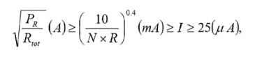
The current through the wiper should be kept low in potentiometers with a carbon or conductive plastic track to minimize noise and wear, preferably with values less than 0.25 mA. Wirewound potentiometers, on the other hand, should draw a certain minimum current through the wiper – more than 0.1 mA – to reduce noise and contact disturbances. The contact resistance in cermet potentiometers has the sensitivity of the metals to small currents and should likewise carry a certain minimum current. An excellent minimum value might be 25 µA. The data sheets also state a maximum current through the wiper, for example, 100 mA at resistances below 100 ohms. At higher resistance values, the contact resistance CR increases, which could lead to local overheating if the wiper current is not kept down.
Thus, the wiper current is determined by the resistance value and nominal power, resistance track material and rotational life (number of shaft turns). In the summary tables, we shall describe some guiding formulas for the wiper current confined within certain limits. The highest limit is the potentiometer’s maximum power current, which may be calculated from the equation.
Next maximum limit – that never must be greater than the maximum power current – is calculated by means of a formula that contains the rotational life N expressed in number of million shaft revolutions (megarevolutions, “MR”) and the resistance in question expressed in kohms. The result is obtained in mA
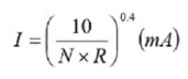
Finally there exists a commonly recommended minimum limit. Example. Suppose a cermet potentiometer with PR = 0.5 W, N = 100 000 revolutions = 0.1 MR, R = 1 MΩ = 1000 kΩ and the minimum limit for cermet = 25 µA. If we insert 0.1 and 1000 respectively in the applicable formula
we obtain
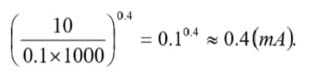
This value is well below the absolute maximum current derived from
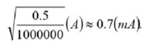
Thus the wiper current should be adjusted to lie between 0.4 mA and 25 µA.


Table 1. TYPE 2 POTENTIOMETERS CHARACTERISTICS
Precision Potentiometers Type 1
Wirewound, Type 1
The disturbances also increase at decreasing temperatures and seem more pronounced when below –30 °C. Thus, the wiper requires a certain current to get a noise-free operation, preferably more than 0.1 mA. Lubricants To reduce wear and prevent oxidation, both on track and wiper, the way is, in most cases, lubricated with some grease or oil. The most common are silicone compounds with relatively constant viscosity over a broad temperature range. The silicones, however, show a rapidly increasing thickness when greases reach temperatures below –5⋅⋅⋅ -15 °C and oils below –30⋅⋅⋅ -40 °C. In addition, at a moderate wiper speed, the wiper tends to slide on top of the lubricant film, causing the ENR values to rise unacceptably. Silicone lubricants have a characteristic that, in specific applications, may be disastrous to the surroundings: they “creep”.
Their surface tension is so low that the lubricant “wets” adjacent surfaces contaminated with a thin film. We talk about a silicone infection. A small dab of grease will, spread over large square meter areas within months. The phenomenon causes problems in the following ways:
- The lubricant film at dry circuit conditions might electrically isolate contaminated surfaces.
- Contaminated contacts with a braking function accompanied by arcovers will be isolated by the silicone granules formed when the miniature arcs decompose the silicone film.
- Contaminated lens systems in high-energy lasers will have their lens surface damaged by the laser beam when it burns the silicone film.
- Glueing of components on contaminated surfaces is made impossible.
Single-Turn
Multi-Turn
On this rotor a slider then travels that makes contact both with the track and the resistance helix. The slider also is supplied with cams that trace against the inner side of the housing and move the slider along the rotor when the shaft is turned. The common number of turns is 3, 5 or 10 but higher numbers exist. The electrical angle is usually defined in multiples of the number of turns. Thus, a 10-turn has an angle of 3600°. That means, among other things, that the resolution becomes better and the setting accuracy greater.
Hybrid Potentiometers
Lubricants on the hybrid track are necessary. Otherwise the track will be worn down after a small fraction of the specified rotational life. The principle for multi-turn constructions might be applied on conductive plastic (CP) if the lacquer isolated copper wire bobbin is directly coated with CP. Use of this process, however, is quite exceptional.

Figure 30. single-turn servo potentiometer

Figure 31. Cutaway view of a multi-turn bushing mount potentiometer. Bourns

Figure 32. Principle of the hybrid potentiometer element.
Non-wire wounds, Type 1
Normally non-wirewound precision potentiometers are manufactured as single-turn devices. Conductive plastic cermet is used, as well as bushing mount styles, in servo applications. The design from Figure 30. could as well be applicable to a nonwirewound servo potentiometer. Just as in servo applications, the rotational life has to be high and puts high demands on the wiper design, the contact pressure and the track, which therefore has to be polished. The polished CP track allows a number of revolutions of several tens of millions.
Then, however, the wiper current must be limited. Otherwise a kind of welding effects on the contact surfaces along the track results, that will destroy both wiper and surface and increase wear and noise. The wiper current should be limited to maximum of 0.25 mA. Example: A serious manufacturer promised a rotational life of 100 x 106 revolutions at 2 mA. But he recommended a maximum wiper current of 10 µA! The 0.25 mA rule, however, is not unconditional. Material, resistance value, nominal power and the number of revolutions of the rotational life come into play. The wiper current in wirewound and cermet potentiometers should comply with Formula 2.
[2]
The contact function of cermet potentiometers is, in its nature, suggestive of that of the metals. Therefore the wiper current should, just as in wirewounds, also be limited in low values. An approximate minimum value might be 25 µA. (Figure 15). In the summary tables, some guiding formulas are stated.
Linear motion potentiometers
A parallel to the slider potentiometer but in Type 1 design is the linear actuated precision potentiometers or linear position transducers. Thus, they have a straight resistance track and a piston or guide bar that holds the wiper and transforms linear motions. The mechanical travels vary between 10 mm and 1.2 m. The resistance tracks are made of wirewound or hybrid elements, of cermet or conductive plastic. As to other parameters they have the same characteristics and specifications that apply to corresponding rotary potentiometers.

Table 2. PRECISION POTENTIOMETERS / TYPE 1 POTENTIOMETERS CHARACTERISTICS
Trimmers

Wirewounds still exist due to their better tolerances and lower TCR. But this design suffers sensitivity to a fundamental mechanical problem. On the one hand, the wire has to be thin to achieve high resistance values; on the other, the contact pressure from the wiper needs to be increased to give a stable setting and a low noise. After a few trim operations, the wire might be pulled in two. Moreover, the corrosion risk is high if moisture gets inside the housing of the trimmer. With the better and better characteristics that characterize the cermet trimmers of today, the need for wire wounds has strongly decreased. If we need better characteristics, we should preferably use metal foil trimmers, despite their higher price. Like conventional potentiometers, trim potentiometers are also encapsulated with O-ring seals for more severe environments.
SM trimmers subjected to washing fluids should have a design that is tight enough to withstand the rinsing process. Otherwise, rinsing products like flux residues may deposit on the track, which can cause severe contact disturbances. Hole mount types may entice someone into bending the leads. Then it is essential that the lead inlets in the potentiometer housing are relieved. Otherwise, forces are easily transferred to the joints with the resistance track and substrate. Consequently, the substrate or the solder joint cracks, thus resulting in an open-circuit.
Regarding cracks, the long multi-turn rectangular 1¼” trimmers of the same basic design as the one in Figure R636 are more sensitive to exterior mechanical forces than the shorter ¾” design. Of course, the latter also has to be handled with care. The ¾” size, fortunately, has more and more replaced the 1¼” style and is being replaced by the more common 3/8” or ½” square styles. The square types exist in single-turn designs and ¼” and 4 mm diameter potentiometers. SMDs exist as single-turn styles in sizes of 3 or 4 mm square, the latter in a multi-turn format, just as hole mount potentiometers, the trimmers are marked with movement direction (Figure 34.).

Figure 34. Circuit diagram with movement direction marked on a trimmer.
The wiper current must not exceed specific specified maximum values that for wire wound and cermet potentiometers may range as high as 100 mA. Furthermore, wiper current should be kept above specific minimum values. B to minimise the noiseoth the maximum and minimum values are determined by rated resistance and track material. The following formulas may serve as guidance simultaneously as they contain certain derating information. If the resistance value in question is called R and is expressed in kΩ when we insert it in the “0.4 power fraction”, we get the following conditions.
Cermet and wire-wound:

Example. R=100 Ω gives I=[100/0.1]0.4 ≈ 16 mA
Carbon track and conductive plastic:

Example. R=100kΩ gives I=[10/100]0.4 ≈ 0.4mA.

Figure 35. Worm gear trimmer. BI Technologies.

Figure 37. Single-turn trimmer. Bourns

Figure 36. Worm gear trimmer. Bourns 3296

Figure 38. Geared spindle drive 1.25 inch potentiometer. Bourns

Source: Passive Blog Components