
A device combining a light-emitting (LED emitter) with a light-sensitive component (Photodetector) in proximity forms a handy pair known as an optocoupler. These devices can also be called optoisolators or photocouplers. Optocouplers let you send digital (and sometimes analog) signals between circuits with separate grounds. And can be used as a switching device or provide “galvanic isolation” between low and high-voltage circuits (essential in circuits that interact with the AC power).
Optocouplers typically provide 2500 volts (rms) isolation, 1012 Ω insulation resistance, and less than a picofarad coupling between input and output. And optocouplers are available in many different packages and configurations. The CTR (Current Transfer Ratio) is one of the main parameters of the device, and it is very much like a gain value for transistors and consists of the collector current (IC) of the output divided by the forward current (IF) of the input and multiplied by 100.

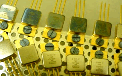
Optocouplers in ceramic LCC-4 and LCC-6 package formats. (Courtesy of Optoi)
There are many types of optocouplers available, each one having an infra-red LED source but with different photo-sensitive configurations, and the choice depends on the intended application. This article will focus on phototransistor output optocouplers for DC circuit-related isolation. These optocouplers have a bipolar transistor output and are intended (most cases) for digital logic level coupling.
1. Phototransistor and phototransistor with base
The base terminal is exposed to address specific design requirements in some phototransistor optocouplers. For example:
- Adding a resistor from base to emitter (or ground) improves the speed (faster switching). The resistor value has to be calculated depending on the specific transistor and the required switching time. This produces a threshold effect because the phototransistor does not begin to conduct until the photodiode current is large enough to produce VBE across the external base resistor. The threshold can be useful in digital applications, but it is an undesirable nonlinearity in analog applications.
- Impulse noise immunity (or reduction) at the output. A capacitor from base to emitter acts as a low pass filter, making smoother the input signal and bypassing sharp spikes due to poor power regulation. However, it reduces signal sensitivity and introduces a delay.
- When multiple optocouplers have to be parallel for design requirements, there will always be some difference in performance between parts, even from the same batch. The exposed bases of these optocouplers can be used for CTR (Current Transfer Ratio) matching.
Left to right: Phototransistor and phototransistor with base configurations
The base terminal in these phototransistors never should be floating if we do not want it acting as an antenna, picking up EMI noise, and transferring it to the output.
If none of the requirements above exist, a base pin could be a better choice. They are usually cheaper than their peers. They will take less space on the board (and less routing, too) as phototransistors without base frequently come in 4 pins package formats instead of the 6-8 pins package formats for the phototransistors with an exposed base terminal.
The OIER10 LCC6 NR (OIER10 LCC6) and the OIER10 LCC4 NR from Optoi are great examples of phototransistors with base terminal and phototransistors configurations.
2. Photo-Darlington Optocouplers
A Darlington transistor is a multi-transistor configuration consisting of two transistor pairs, where one transistor controls the other transistor’s base. In this configuration, the current amplified by the first transistor is amplified further by the second one. The collectors of both transistors are connected. This configuration has a much higher current gain than each transistor taken separately. It was invented in 1953 by Sidney Darlington.
In the photo-Darlington transistor configuration, the first transistor acts as the photodetector, and its emitter is coupled into the base of the second transistor. This gives a much higher level of gain as the main characteristic of this configuration. With LED-phototransistor pairs is possible to get CTRs of 100% or more, while with LED-photo-Darlingtons, you can get CTRs of 500% or more; however, these are very much slower than the ordinary phototransistors, having a maximum frequency of around 20 kHz.

Photo-Darlington configuration
Wrapping Up
There are available many types of optocoupler configurations. This article is centered on phototransistor output optocouplers used for DC isolation.
Configurations with a single transistor are divided in two. Both configurations have a single transistor, with the only difference being that one of them has an exposed base terminal. Both solutions are acceptable, but if your design does not require a base terminal (more complex design), a part without a base pin could be a better choice since they are usually cheaper.
Photo-Darlington optocouplers provide a very much higher level of gain, but they are very much slower than ordinary phototransistors.
More about Optocouplers?
Optoi is an Italian Company dealing with optoelectronics and microelectronics. In 2011, among the rapidly growing activities involving the Company’s aerospace unit, the company started a new development centered on a radiation-tolerant optocoupler.
This activity was funded by European Component Initiative (ECI) – ESA. It was focused on developing a European optocoupler with its European-Space-Component-Coordination (ESCC) evaluation for space applications, keeping the performances of the non-European counterparts as reference.
In 2021, Optoi, being Europe’s leading optocoupler alternative thanks to ESA support, joined ALTER to promote its products and include them on doEEEt.com’s database, possibly requesting samples for evaluation of Optoi’s optocouplers.
Javier de la Ossa Fernández
A data scientist with a decade of experience in aerospace and high-reliability industries, now specializing in digital marketing and analytics. Armed with a background in Electronics Engineering, applies AI and data-driven strategies to deliver innovative and impactful solutions.
Related Articles

The GRACE project: Electrical characterization at 500°C
The GRACE project develops SiC radiation sensors for plasma diagnostics, tested at 500°C to ensure fusion reactor suitability.
Thermal Vacuum for HV Optocouplers
HV optocouplers require thermal vacuum testing to ensure isolation reliability, as vacuum can affect internal gel stability and performance.
SIC diodes versus Heavy Ions (SEE)
SiC diodes offer high-performance switching for space use, with radiation effects manageable through proper testing and bias control.