The use of COTS in space is a reality nowadays, and Optoelectronics is no exception. In the case of LEDs, technological improvements and new developments make them the best (or even the only) option to address a technological problem.
This quick evolution of the devices enhances the typical problems of COTS. Due to improvements in technology, many changes are made quickly in specs, making it harder to get traceability from the manufacturer and retailers. These devices are also often high-performance but not high reliability and were designed to withstand terrestrial conditions but not space.
Introducing the usage in planetary exploration as illumination of the surface in robotic lunar exploration needs new testing techniques. Commercial LEDs are available in many packages, most with SMD mounting, and, in many cases, finished with a silicone glob top, as shown in Fig. 1. The degradation caused by lunar regolith exposure to all these options is unknown and shall be assessed by testing.
This paper presents and explains the regolith test setup developed by ALTER. Design and development of the test setup have taken into consideration not only the requirements of the regolith test itself but the necessity of being compatible with the remaining tests necessary to be performed onto the same part types for ECSS-based space qualification.
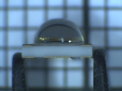
Figure 1. Example of SMD Globtop package
Test considerations and results
The test setup design and method aimed to most realistically obtain the exposure of LEDs to lunar regolith while biased in vacuum conditions. However, many other considerations had to be taken into account to obtain as much information as possible and be compatible with many other space-grade tests to be performed on other samples of the same LEDs while keeping reasonable costs and time scales.
- LEDs will be exposed to lunar regolith in operating conditions. Certain devices need to be biased with currents as high as 1.5A. Electrical power through vacuum feed-throughs shall be addressed, and thermal management inside the chamber should be done because heat has dissipated.
- Samples shall be tested in lots of several samples to keep testing time and cost at a minimum while ensuring good homogeneity of the results.
- DUTs are SMD packages that shall be mounted onto boards to be handled and biased, as shown in Fig. 2. To allow correct heat management, each manufacturer’s footprint and mounting instructions shall be used. These boards shall be compatible with the same characterization and regolith test setup to test many samples without modifying test setups.
- Mass measurements will be performed with electro-optical characterisation to evaluate the amount of regolith attached to the samples. Samples shall be singulated to allow single-sample measurements and mass measurements. Biasing shall be performed so that no mass is added nor removed to the single LED board, so no wires or welding are possible.
- Electro-optical characterization of the samples must be performed at room temperature before the regolith test. Also, mass (sample + individual board) is weighed using a 0.1mg accuracy system.
- The correct electrical connection of the samples inside the test setup shall be checked before any regolith is put in place (fig.3). Then, enough lunar regolith shall be placed in the specific area of the test setup. The quantity of regolith impacts not only the quantity deposited but also the homogeneity of the deposition. This effect shall be carefully evaluated when several samples are tested at a time.
- A vacuum gauge shall be implemented in order to verify that the pressure level is not changing during the test due to any lack of hermeticity of the setup (might be caused by lunar regolith itself in o-rings or similar) as shown in fig.4.
- Since the test shall be performed in representative conditions, samples shall be electrically biased a while in advance to the test with nominal current values until thermal, and hence, voltage stabilization is achieved, and voltage monitoring stabilization shall be achieved.
- Devices are removed from the regolith setup and weighted before the electro-optical characterization to correctly evaluate the quantity of dust attached.
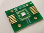
Figure 2. ATN test board with central footprint customized for each type of LED
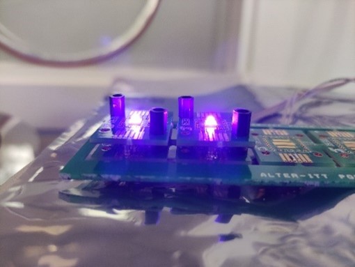
Figure 3. Blue LEDs biased on using the setup test board with spring contact connections
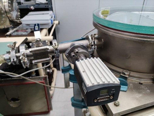
Figure 4. Vacuum gauge for pressure monitoring
Test considerations and results
Lunar regolith was homogeneously deposited onto the devices, and the effectiveness of the optical power was confirmed in a preliminary trial. The lunar regolith simulant used in the tests stuck to all the surfaces of the devices under test and boards, as can be seen in Fig. 5.
The variation in degradation introduced by regolith can and will be stunned, varying the quantity of regolith in additional trials to obtain as much information as possible in the testing phase.
Versatile setup and sample mounting methods shall be implemented to optimize testing while many different sample types will be tested.
The setup developed in ALTER Optoelectronics and New Technologies laboratory fulfills all the requirements and will be used to evaluate the robustness of commercial LEDs against lunar regolith.
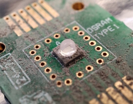
Figure 5. LED and test board after regolith testthe tests sticks to all the surfaces of the devices under test and boards, as can be seen in fig. 5.
