This article introduces EMI Filtering, how it works, and its performance.
With the ever-increasing use of electronic equipment comes a greater likelihood of interference from all the other equipment. Similarly, we’re seeing more circuits with lower power levels that are easily disturbed, so there’s a need to protect equipment from EMI (electromagnetic interference). In automotive or medical applications, for example, there can be no false alarms due to external interference. The level of uncertainty has pushed EMI compliance testing to the component level.
EMI filtering is an essential element of equipment design to meet international legislation such as the EU Directive on EMC or the FCC. Introducing screening measures to cases or cables, for example, may suffice in many instances, but you might need to introduce low-pass filtering for additional protection as well. Here, we will explore EMI filtering and the terminology for designing effective protection.
Input / Output cabling
In an ideal situation, a Faraday Cage would protect a piece of equipment or circuit from EMI by enclosing it in a metal (or conductive box) and preventing interference. However, most equipment require input and/or output connections for power cables or signal control lines. The cables providing these connections can act as antennae that can pick up interference and radiate it, see Figure 1.
Subsequently, the following can occur:
- Interference can enter equipment directly through the cabling (conducted interference).
- Radiated interference can travel directly to the affected equipment.
- Interference can exit an EMI source via a cable and subsequently be radiated from the cable and to the affected equipment.
- Interference can be radiated from an EMI source and picked up by a cable entering the affected equipment.
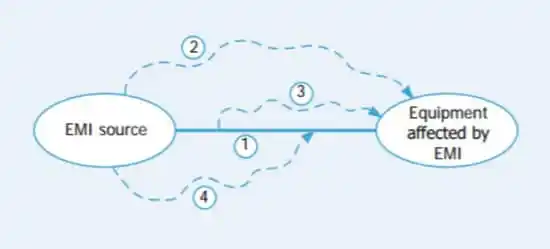
Figure 1: Modes of propagation of EMI
Filter Location
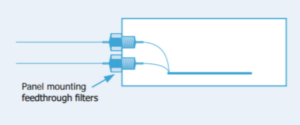
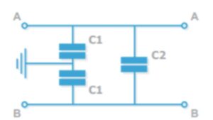
Filter Location matters when preventing interference from entering or leaving a piece of equipment. With panel mount filters, feedback through EMI filters can be mounted on the wall of a shielded case; see Figure 2. All incoming or outgoing cables would then pass through the filters. Power, or any other wanted signals, pass through the filters unaffected, whereas higher frequency interference is removed. The screened case protects against radiated interference, and feedthrough filters protect against conducted interference. Combined, the integrity of the equipment is assured.
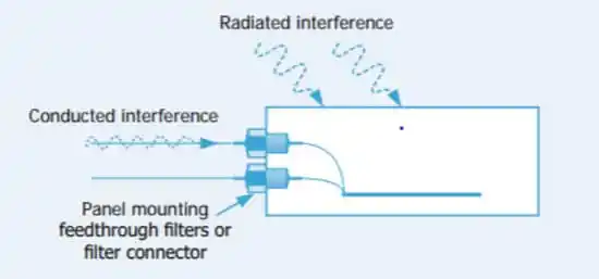
Figure 2: Feedthrough filters remove conducted interference and provide ultimate performance
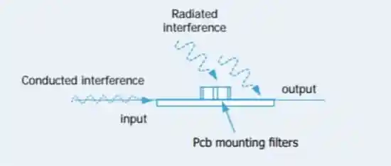
Figure 3: Surface mount filters remove conducted interference, performance reduced due to radiated interference
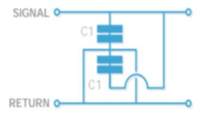
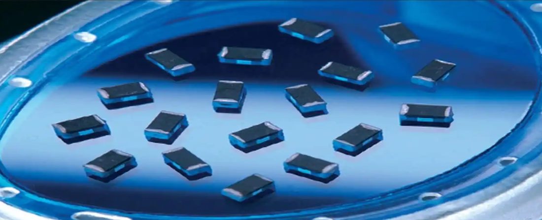
Surface-Mount Filters (see Figure 3) are an effective option when there is no suitable bulkhead for mounting filters. In general, insertion loss performance is reduced at higher frequencies unless additional screening measures are taken. Thoughtful design practices, including short tracks and connections, good grounding, and proximity to input, will help improve insertion loss performance.
Common Terms
The following chart provides a foundational understanding of common terms used when designing and implementing EMI filters.
Resource: EPCI


