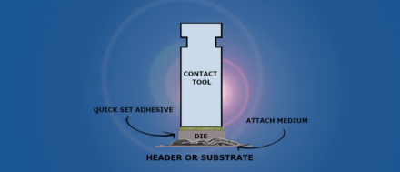
Failure Analysis

for Electronic Components

Failure analysis is the process of analysing the component data or the component itself to determine the reason(s) for degraded performance or catastrophic failure of a component either, during component manufacturing and testing, during incoming inspection, or after delivery to the customer, at the final application. Since there are an infinite number of variables in play at any one time, it is important as the first step in any failure analysis to understand how and when the failure occurred.

The accumulated experience of ALTER TECHNOLOGY on evaluation, screening, lot validation and testing of different families of EEE parts, has made us to acquire a huge expertise and knowledge about the behavior/performance of the EEE components, the associated failure modes and possible root causes.

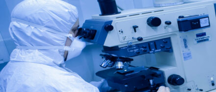
Alter Technology offers a full set of verification and testing activities to perform a failure analysis on your EEE components, so that can be determined the origin of the observed failure mechanism.

doEEEt, in addition to the HIGH RELIABILITY and SPACE EEE components cataloging, also includes many different documents such as Part Specifications, Test Methods, Reports, Manufacturers Notifications … that helps you to better understand the component.

So it is important to know as much detailed information as possible, i.e., Failure Analysis, helps … how the component was procured, how it was stored before delivery, how it was handled, its location in the circuit (if mounted), how it was biased, and for how long, environmental conditions, failure mode or degraded performance etc. Being aware of all these variables can help to focus on the failure analysis process. From this preliminary assessment, a systematic failure analysis test sequence can be formulated and performed to establish the root cause of the failure.
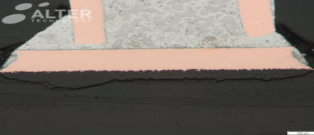
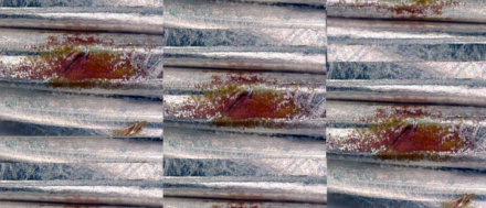
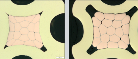
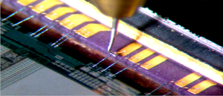
The test flow may include destructive and non-destructive testing and is defined to systematically identify possible failure mechanisms, which as the analysis proceeds reduce the permutations for the cause of failure. The longer the failure analysis proceeds, the deeper it can go into the device construction, starting from the external appearance to the internal construction and reverse engineering of the part-down to the fabrication of the part.

Portfolio
JANTXV4N49 Optocoupler showing a detached bonding during the internal visual inspection.

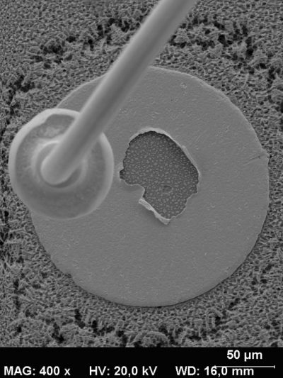
To determine the root cause of a failure, advanced analysis techniques may be employed not just to verify compliance of the part to defined assembly and test methods but to determine the origin of the observed failure mechanism.

This activity requires a high level of experience and expertise and provides added value at different levels:

  • At the component manufacturer. Identifying problems with raw materials, handling, manufacturing processes, testing, etc., that can be improved, increasing the production yield and product quality.
  • At component user level. Knowing the problem origin, and being able to provide solutions to prevent recurrence-applying the correct risk mitigation techniques for each application/need.
  • Sometimes the problem is directly related to the component, and depending on the failure mechanism, corrective actions can be implemented as follows:
    • to change the supplier,
    • to replace the type by a more adequate one,
    • to replace the lot,
    • to re-screen/test to remove the bad/weak unit, etc.

Proposals can also be provided at the equipment level, sometimes the origin of the failures are not linked to the component itself, but are due to a bad component selection, poor use of derating rules, external electrical over-stresses, etc. Identification of such problems is essential to the user in order to allow them to improve the equipment quality and reliability. doEEEt, our tool for HI-REL EEE Parts for space application, provides you the most complete and updated information about Hi-Rel EEE parts

GET IN TOUCH TODAY!
Do you have questions? Contact us!

Below is an example of a failure analysis test flow for integrated circuits:

  • External (visual) examination. To check the conditions of the external package, seals, etc.
  • Electrical test verification. Not limited to electrical parametric test but oriented to characterize the electrical behavior of the suspect or failed parts. Specific electrical test equipment shall be used depending on the device type, e.g. curve tracer.
  • Metallurgical Analysis
  • Metallography and Cross-sectioning
  • Scanning Electron Microscope (SEM) services
  • FTIR Spectroscopy (Fourier Transform Infrared Spectroscopy) for identification of organic materials
  • Scanning Acoustic Microscopy (C-Mode) for identifying fractures, voiding, delamination, and imaging internal features within a component
  • Mechanical Testing (tension, compression, shear)
  • Vibration and Fatigue Testing
  • Electronic Component Parametric Testing from DC to RF
  • Electronic Component Digital and Analog Curve Tracing
  • Electronic Component Functional Testing
  • Real Time Micro Focus X-ray Inspection (2D and 3D)
  • Component Decapsulation and Delidding
  • Solderability Testing
  • Analysis to determine the cause of poor solderability
  • Plating and Coating Thickness Measurement
  • Screening of Electronic Components (Visual Inspection, Electrical Test, X-ray and SAM)
  • Fine and gross leak test. Will determine if the device hermeticity has been violated and the risk of moisture or external contaminants ingression.
  • Acoustic Microscopy Inspection (C.S.A.M.). This technique is especially useful for plastic encapsulated packages to determine the existence of delamination between materials. It is a natural complement to the X-ray inspection technique.
  • Particle Impact Noise Detection (P.I.N.D.) is a test performed on components with internal cavities to determine if there are any soft or hard particles inside
  • Opening / de-lidding, to expose the active element of the component for internal visual (optical) inspection. Different techniques are available: mechanical de-capping, plasma etching, chemical attack, etc.
  • Internal visual (optical) inspection. Different optical methods and equipment are required to cover the magnification range needed to identify any defect: bright and dark fields, Nomarski optic, polarizer, etc.
Portfolio
Sample showing a broken wire at the bonding pad

Failures most commonly occur near the beginning (failures caused by latent defects) and near the ending of the lifetime of the parts (failures caused by wear out), resulting in the bathtub curve graph of failure rates. A number of techniques can be considered for detecting defective parts in the lot at the earliest stage, such as burn-in, implemented for high-reliability parts. There are also failures caused by improper handling, storage, packaging, mounting, by radiation, etc.

ALTER TECHNOLOGY LABORATORY SERVICES

Bond Pull Test

Jesús Enrique Barbero Muñoz
0
Bond Pull Test
The purpose of Bond Pull Test is to measure bond strengths, to evaluate bond strength distributions and to determine compliance with specifi...
doEEEt.com